Advertisements
Advertisements
प्रश्न
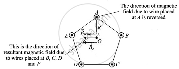
Five long wires A, B, C, D and E, each carrying current I are arranged to form edges of a pentagonal prism as shown in figure. Each carries current out of the plane of paper.

- What will be magnetic induction at a point on the axis O? AxisE is at a distance R from each wire.
- What will be the field if current in one of the wires (say A) is switched off?
- What if current in one of the wire (say) A is reversed?
Advertisements
उत्तर
a. The wires shown in this problem carrying current outwards to the plane. And we know that direction of magnetic field is perpendicular to both current and position vector r. So, the vector sum of magnetic field produced by each wire at O is equal to 0.
Suppose the five wires A, B, C, D and E be perpendicular to the plane of paper at locations as shown in figure.
Thus, magnetic field induction due to five wires will be represented by various sides of closed pentagon in one order, lying in the plane of paper. So, its value is zero.
b. When current in AA' is switched off, then B1 = 0 and resultant becomes
R = B2 + B3 + B4 + B5
But form (a) part B1 + B2 + B3 + B4 + B5 = 0
Or `vecB_2 + vecB_3 + vecB_4 + vecB_5 = - vecB_1`
R = – B1
R = `(mu_0I)/(2pir)`
i.e. Direction of resultant is opposite to `vecB_1`.
c. If current in wire A is reversed, then
Total magnetic field induction at O = Magnetic field induction due to A + Magnetic field induction due to wires B, C, D and E
= `(mu_0)/(4piR) (2I)/R` (acting perpendicular to AO towards left) + `(mu_0)/pi (2I)/R` (acting perpendicular AO towards left)
= `(mu_0I)/(piR)` acting perpendicular AO towards left.
APPEARS IN
संबंधित प्रश्न
How does one understand this motional emf by invoking the Lorentz force acting on the free charge carriers of the conductor? Explain.
Two long straight parallel conductors 'a' and 'b', carrying steady currents Ia and Ib are separated by a distance d. Write the magnitude and direction of the magnetic field produced by the conductor 'a' at the points along the conductor 'b'. If the currents are flowing in the same direction, what is the nature and magnitude of the force between the two conductors?
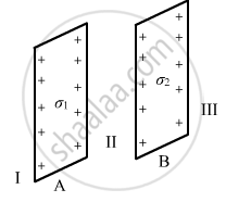
Two infinitely large plane thin parallel sheets having surface charge densities σ1 and σ2 (σ1 > σ2) are shown in the figure. Write the magnitudes and directions of the net fields in the regions marked II and III.
Derive the expression for force per unit length between two long straight parallel current carrying conductors. Hence define one ampere.
Two parallel, long wires carry currents i1 and i2 with i1 > i2. When the currents are in the same direction, the magnetic field at a point midway between the wires is 10 µT. If the direction of i2 is reversed, the field becomes 30 µT. The ratio i1/i2 is
A long, straight wire of radius r carries a current i and is placed horizontally in a uniform magnetic field B pointing vertically upward. The current is uniformly distributed over its cross section. (a) At what points will the resultant magnetic field have maximum magnitude? What will be the maximum magnitude? (b) What will be the minimum magnitude of the resultant magnetic field?
Figure shows a metallic wire of resistance 0.20 Ω sliding on a horizontal, U-shaped metallic rail. The separation between the parallel arms is 20 cm. An electric current of 2.0 µA passes through the wire when it is slid at a rate of 20 cm s−1. If the horizontal component of the earth's magnetic field is 3.0 × 10⁻⁵ T, calculate the dip at the place.
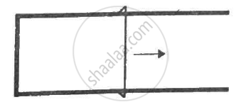
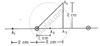
Figure shows two parallel wires separated by a distance of 4.0 cm and carrying equal currents of 10 A along opposite directions. Find the magnitude of the magnetic field B at the points A1, A2, A3.
Two long, straight wires, each carrying a current of 5 A, are placed along the x- and y-axis respectively. The currents point along the positive directions of the axes. Find the magnetic fields at the points (a) (1 m, 1 m), (b) (−1 m, 1 m), (c) (−1 m, −1 m) and (d) (1 m, −1 m).
Answer the following question.
Two infinitely long straight wire A1 and A2 carrying currents I and 2I flowing in the same direction are kept' distance apart. Where should a third straight wire A3 carrying current 1.5 I be placed between A1 and A2 so that it experiences no net force due to A1 and A2? Does the net force acting on A3 depend on the current flowing through it?
According to Ampere's circuital law, ______.
Beams of electrons and protons move parallel to each other in the same direction. They ______.
Two long parallel wires kept 2 m apart carry 3A current each, in the same direction. The force per unit length on one wire due to the other is ______.
The figure below are two long, parallel wires carrying current in the same direction such that I1 < I2.

- In which direction will wire I1 move?
- If the direction of the current I2 is reversed, in which direction will the wire I1 move now?
When two long, straight, current-carrying conductors are placed parallel to each other and the currents flow in the same direction, the conductors:
By symmetry, the magnetic field of conductor b exerts a force on conductor a. The relationship between the two forces Fba and Fab is:
If the current Ia in conductor a is doubled while Ib and the distance d remain unchanged, the force per unit length F/L between the conductors:
If the perpendicular distance d between two parallel current-carrying conductors is doubled, the force per unit length F/L:
A wire carrying a current of 1 A flows East → West in a region where the horizontal component of Earth's magnetic field is B = 3.0 × 10⁻⁵ T directed South → North. The force per unit length on the wire is:
