Advertisements
Advertisements
प्रश्न
Do the electrodes in an electrolytic cell have fixed polarity like a battery?
Advertisements
उत्तर
No, the electrodes in an electrolytic cell do not have fixed polarity like that of a battery. If we take an electrolytic cell consisting of the Ag electrodes and the AgNO3 as electrolyte. When the battery is connected to it, the end to which the positive terminal of the battery is connected is the anode and the end to which the negative terminal is connected is the cathode.
\[{NO}_3^-\] ions are deposited at the anode and Ag+ ions are deposited at the cathode. When the connection of the electrolytic cell is reversed, the polarities of the electrodes are also reversed.
APPEARS IN
संबंधित प्रश्न
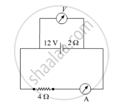
A battery of emf 12 V and internal resistance 2 Ω is connected to a 4 Ω resistor as shown in the figure.
(a) Show that a voltmeter when placed across the cell and across the resistor, in turn, gives the same reading.
(b) To record the voltage and the current in the circuit, why is voltmeter placed in parallel and ammeter in series in the circuit?
Distinguish between emf and terminal voltage of a cell.
A battery of emf 10 V and internal resistance 3 Ω is connected to a resistor. If the current in the circuit is 0.5 A, what is the resistance of the resistor? What is the terminal voltage of the battery when the circuit is closed?
In a potentiometer arrangement, a cell of emf 1.25 V gives a balance point at 35.0 cm length of the wire. If the cell is replaced by another cell and the balance point shifts to 63.0 cm, what is the emf of the second cell?
A secondary cell after long use has an emf of 1.9 V and a large internal resistance of 380 Ω. What maximum current can be drawn from the cell? Could the cell drive the starting motor of a car?
In a potentiometer arrangement for determining the emf of a cell, the balance point of the cell in open circuit is 350 cm. When a resistance of 9 Ω is used in the external circuit of the cell, the balance point shifts to 300 cm. Determine the internal resistance of the cell.
A resistor R is connected to a cell of-emf e and internal resistance r. The potential difference across the resistor R is found to be V. State the relation between e, V, Rand r.
A potentiometer wire of length 1.0 m has a resistance of 15 Ω. It is connected to a 5 V battery in series with a resistance of 5 Ω. Determine the emf of the primary cell which gives a balance point at 60 cm.
A cell of emf ‘E’ and internal resistance ‘r’ draws a current ‘I’. Write the relation between terminal voltage ‘V’ in terms of E, I and r ?
A rectangular conductor LMNO is placed in a uniform magnetic field of 0.5 T. The field is directed perpendicular to the plane of the conductor. When the arm MN of length of 20 cm is moved towards left with a velocity of 10 ms−1, calculate the emf induced in the arm. Given the resistance of the arm to be 5 Ω (assuming that other arms are of negligible resistance) find the value of the current in the arm.

A cell of emf E and internal resistance r is connected to two external resistance R1 and R2 and a perfect ammeter. The current in the circuit is measured in four different situations:
(i) without any external resistance in the circuit
(ii) with resistance R1 only
(iii) with R1 and R2 in series combination
(iv) with R1 and R2 in parallel combination
The currents measured in the four cases are 0.42 A, 1.05 A, 1.4 A and 4.2 A, but not necessarily in the order. Identify the currents corresponding to the four cases mentioned above.
A cell of emf ‘E’ and internal resistance ‘r’ is connected across a variable resistor ‘R’. Plot a graph showing the variation of terminal potential ‘V’ with resistance R. Predict from the graph the condition under which ‘V’ becomes equal to ‘E’.
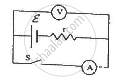
The following figure shows an arrangement to measure the emf ε and internal resistance r of a battery. The voltmeter has a very high resistance and the ammeter also has some resistance. The voltmeter reads 1.52 V when the switch S is open. When the switch is closed, the voltmeter reading drops to 1.45 V and the ammeter reads 1.0 A. Find the emf and the internal resistance of the battery.
How many time constants will elapse before the power delivered by a battery drops to half of its maximum value in an RC circuit?
Answer the following question.
A cell of emf E and internal resistance r is connected across a variable resistor R. Plot the shape of graphs showing a variation of terminal voltage V with (i) R and (ii) circuit current I.
A cell having an emf E and internal resistance r is connected across a variable external resistance R. As the resistance R is increased, the plot of potential difference V across R is given by ______.
A block of metal is heated directly by dissipating power in the internal resistance of block. Because of temperature rise, the resistance increases exponentially with time and is given by R(t) = 0.5 e2t, where t is in second. The block is connected across a 110 V source and dissipates 7644 J heat energy over a certain period of time. This period of time is ______ × 10-1 sec (take ln 0.367 = -1).
