Advertisements
Advertisements
प्रश्न
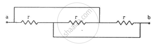
Find the equivalent resistance of the network shown in the figure between the points a and b.
Advertisements
उत्तर
The simplified circuit can be drawn as shown below.
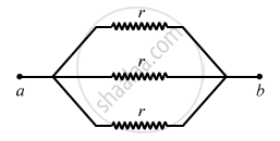
Equivalent resistance \[= \frac{1}{\frac{1}{r} + \frac{1}{r} + \frac{1}{r}} = \frac{r}{3}\]
APPEARS IN
संबंधित प्रश्न
Two identical cells of emf 1.5 V each joined in parallel, supply energy to an external circuit consisting of two resistances of 7 Ω each joined in parallel. A very high resistance voltmeter reads the terminal voltage of cells to be 1.4 V. Calculate the internal resistance of each cell.
A cell of emf 'E' and internal resistance 'r' is connected across a variable resistor 'R'. Plot a graph showing variation of terminal voltage 'V' of the cell versus the current 'I'. Using the plot, show how the emf of the cell and its internal resistance can be determined.
The storage battery of a car has an emf of 12 V. If the internal resistance of the battery is 0.4 Ω, what is the maximum current that can be drawn from the battery?
In a potentiometer arrangement, a cell of emf 1.25 V gives a balance point at 35.0 cm length of the wire. If the cell is replaced by another cell and the balance point shifts to 63.0 cm, what is the emf of the second cell?
In a potentiometer arrangement for determining the emf of a cell, the balance point of the cell in open circuit is 350 cm. When a resistance of 9 Ω is used in the external circuit of the cell, the balance point shifts to 300 cm. Determine the internal resistance of the cell.
A resistor R is connected to a cell of-emf e and internal resistance r. The potential difference across the resistor R is found to be V. State the relation between e, V, Rand r.
A potentiometer wire of length 1.0 m has a resistance of 15 Ω. It is connected to a 5 V battery in series with a resistance of 5 Ω. Determine the emf of the primary cell which gives a balance point at 60 cm.
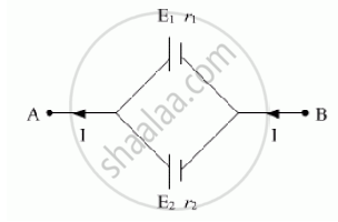
Two cells of emf E1, E2 and internal resistance r1 and r2 respectively are connected in parallel as shown in the figure.
Deduce the expressions for
(1) the equivalent e.m.f of the combination
(2) the equivalent resistance of the combination, and
(3) the potential difference between the point A and B.
How many time constants will elapse before the power delivered by a battery drops to half of its maximum value in an RC circuit?
Five cells each of emf E and internal resistance r send the same amount of current through an external resistance R whether the cells are connected in parallel or in series. Then the ratio `("R"/"r")` is:
Two batteries of emf ε1 and ε2 (ε2 > ε1) and internal resistances r1 and r2 respectively are connected in parallel as shown in figure.

A cell of emf E and internal resistance r is connected across an external resistance R. Plot a graph showing the variation of P.D. across R, versus R.
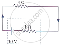
The terminal voltage of the battery, whose emf is 10 V and internal resistance 1 Ω, when connected through an external resistance of 4 Ω as shown in the figure is:
Internal resistance of a cell is the resistance offered by which component?
When a cell is short-circuited (R = 0), the maximum current that can flow is:
During charging of a cell, the current direction enters through:
During discharging, chemical energy is converted to:
Internal resistance of a cell increases when the distance between electrodes:
