Advertisements
Advertisements
प्रश्न
Explain about domestic electric circuits. (circuit diagram not required)
Advertisements
उत्तर
In our homes, electricity is distributed through the domestic electric circuits wired by the electricians. The first stage of the domestic circuit is to bring the power supply to the main box from a distribution panel, such as a transformer. The important components of the main box are: (i) a fuse box and (ii) a meter. The meter is used to record the consumption of electrical energy. The fuse box contains either a fuse wire or a Miniature Circuit Breaker (MCB). The function of the fuse wire or an MCB is to protect the household electrical appliances from overloading due to excess current.
An MCB is a switching device, which can be activated automatically as well as manually. It has a spring attached to the switch, which is attracted by an electromagnet when an excess current passes through the circuit. Hence, the circuit is broken and the protection of the appliance is ensured.
The electricity is brought to houses by one wire that has red insulation and is called the ‘live wire’. The other wire has black insulation and is called the ‘neutral wire’. The electricity supplied to your house is actually an alternating current having an electric potential of 220 V. Both, the live wire and the neutral wire enter into a box where the main fuse is connected with the live wire. After the electricity meter, these wires enter into the main switch, which is used to discontinue the electricity supply whenever required. After the main switch, these wires are connected to live wires of two separate circuits.
Out of these two circuits, one circuit is of a 5 A rating, which is used to run the electric appliances with a lower power rating, such as tube lights, bulbs, and fans. The other circuit is of a 15 A rating, which is used for two insulated wires. Out of these two wires, run electric appliances with a high power rating, such as air-conditioners, refrigerators, electric iron, and heaters. It should be noted that all the circuits in a house are connected in parallel so that the disconnection of one circuit does not affect the other circuit. One more advantage of the parallel connection of circuits is that each electric appliance gets an equal voltage.
APPEARS IN
संबंधित प्रश्न
Explain with the help of a labelled circuit diagram how you will find the resistance of a combination of three resistors, or resistance R1, R2 and R3, joined in parallel. Also mention how you will connect the ammeter and the voltmeter in the circuit when measuring the current in the circuit and the potential difference across one of the three resistors of the combination.
In an electric circuit, electron flow a from of point of ______ potential to the point of ______ potential.
Explain the following:
Open circuit
The unit of electrical power is _______.
Right or wrong sentence.
Increasing the current passing through the wire decreases the magnetic field intensity.
What is the use of earthing wire?
Rahul wants to make an electric circuit. He has a bulb, two wires, a safety pin, and a piece of copper. He does not have any electric cell or battery. Suddenly he gets some idea. He uses lemon instead of a battery and makes a circuit. Will the bulb glow?
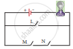
In the circuit shown, which switches (L,M or N) must be closed to light up the bulb?
Draw a circuit diagram of an electric circuit containing a cell, a key, an ammeter, a resistor of 2 Ω in series with a combination of two resistors (4 Ω each) in parallel and a voltmeter across the parallel combination. Will the potential difference across the 2 Ω resistor be the same as that across the parallel combination of 4 Ω resistors? Give reason.
