Advertisements
Advertisements
प्रश्न
Explain about domestic electric circuits. (circuit diagram not required)
Advertisements
उत्तर
In our homes, electricity is distributed through the domestic electric circuits wired by the electricians. The first stage of the domestic circuit is to bring the power supply to the main box from a distribution panel, such as a transformer. The important components of the main box are: (i) a fuse box and (ii) a meter. The meter is used to record the consumption of electrical energy. The fuse box contains either a fuse wire or a Miniature Circuit Breaker (MCB). The function of the fuse wire or an MCB is to protect the household electrical appliances from overloading due to excess current.
An MCB is a switching device, which can be activated automatically as well as manually. It has a spring attached to the switch, which is attracted by an electromagnet when an excess current passes through the circuit. Hence, the circuit is broken and the protection of the appliance is ensured.
The electricity is brought to houses by one wire that has red insulation and is called the ‘live wire’. The other wire has black insulation and is called the ‘neutral wire’. The electricity supplied to your house is actually an alternating current having an electric potential of 220 V. Both, the live wire and the neutral wire enter into a box where the main fuse is connected with the live wire. After the electricity meter, these wires enter into the main switch, which is used to discontinue the electricity supply whenever required. After the main switch, these wires are connected to live wires of two separate circuits.
Out of these two circuits, one circuit is of a 5 A rating, which is used to run the electric appliances with a lower power rating, such as tube lights, bulbs, and fans. The other circuit is of a 15 A rating, which is used for two insulated wires. Out of these two wires, run electric appliances with a high power rating, such as air-conditioners, refrigerators, electric iron, and heaters. It should be noted that all the circuits in a house are connected in parallel so that the disconnection of one circuit does not affect the other circuit. One more advantage of the parallel connection of circuits is that each electric appliance gets an equal voltage.
APPEARS IN
संबंधित प्रश्न
Draw circuit symbols for
A closed switch
In an electric circuit, a battery and a bulb have been connected and the battery consists of two cells of equal potential difference. If the bulb is not glowing, then which tests will you perform in order to find out the reason for the bulb not glowing?
In the circuit diagram below, 10 units of electric charge move past point x every second What is the current in the circuit ______.
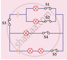
Study the electric circuit below. Which of the following switches should be closed so that only two bulbs will light up
Fuse is
State whether true or false. If false, correct the statement.
Ammeter is connected in parallel in any electric circuit.
A child has drawn the electric circuit to study Ohm’s law as shown in Figure. His teacher told that the circuit diagram needs correction. Study the circuit diagram and redraw it after making all corrections.

When an electric current flows through a copper wire AB as shown in the following figure, the wire

Draw the symbols of the following circuit components.
Switch in off position
Assertion: People struck by lightning receive a severe electrical shock.
Reason: Lightning carries very high voltage.
