- A d.c. A motor works on the principle that a current-carrying conductor placed normally in a magnetic field experiences a force, producing rotational motion.
- The split ring commutator reverses the direction of current in the coil after every half rotation, so that the coil continues to rotate in the same direction.
- The armature coil experiences an anticlockwise couple due to equal and opposite forces on its arms, causing continuous rotation of the coil.
- In a d.c. Motor, electrical energy supplied by the battery is converted into mechanical energy.
Definitions [12]
Definition: Oersted's Experiment
Oersted's Experiment demonstrated that a current-carrying conductor produces a magnetic field around itself, proving that moving electric charges (current) generate magnetism.
Definition: Right Hand Thumb Rule
If a current-carrying straight conductor is held in the right hand such that the thumb points in the direction of the electric current, then the fingers curled around the conductor show the direction of the magnetic field.
This is called the Right-Hand Thumb Rule.
OR
If you hold a current-carrying conductor in your right hand with the thumb pointing in the direction of the current, then the curled fingers show the direction of the magnetic field (lines of force) around the conductor.
Definition: Solenoid
A long, cylindrical coil consisting of a large number of closely wound circular turns of insulated copper wire, in which a magnetic field is produced when current flows through it.
Definition: Electromagnet
An electromagnet is a temporary strong magnet made by passing current in a coil wound around a piece of soft iron. It is an artificial magnet.
Definition: Permanent Magnets
Substances which at room temperature retain their ferromagnetic property for a long period of time are called permanent magnets.
Definition: Simple D.C. Motor
An electric motor is a device which converts the electrical energy into the mechanical energy.
Definition: Electromagnetic Induction
The phenomenon in which electric current is generated in a conductor or closed coil due to a varying magnetic field is called electromagnetic induction.
Definition: Faraday's Law of Induction
Whenever the number of magnetic lines of force (magnetic flux) passing through a coil changes, an electric current is induced in the coil. This current is called the induced current.
Define the right-hand thumb rule.
If the current-carrying conductor is held in the right hand such that the thumb points in the direction of the current, then the direction of the curl of the fingers will give the direction of the magnetic field.
Definition: A.C. Generator
An a.c. generator is a device which converts the mechanical energy into the electrical energy using the principle of electromagnetic induction.
Definition: Transformer
An electrical device which converts low alternating voltage at high current to high alternating voltage at low current (or vice versa) — i.e., a device which reduces or increases the voltage in an AC circuit through mutual induction — is called a transformer.
Define a Transformer.
The transformer is a device used for converting low voltage into high voltage and high voltage into low voltage. It works on the principle of electromagnetic induction.
Formulae [4]
Formula: Turns Ratio / Voltage Ratio
\[\frac{V_s}{V_p}=\frac{N_s}{N_p}=k\]
Where:
- Vs = Secondary (output) voltage (V)
- Vp = Primary (input) voltage (V)
- Ns = Number of turns in secondary coil
- Np = Number of turns in primary coil
- k = Transformation ratio (turns ratio)
Formula: Current Ratio (Ideal Transformer)
\[\frac{I_p}{I_s}=\frac{N_s}{N_p}=\frac{V_s}{V_p}\]
Formula: Combined Transformer Equation
\[\frac{V_s}{V_p}=\frac{N_s}{N_p}=\frac{I_p}{I_s}=k\]
Formula: Ideal Transformer
Pinput = Poutput
Theorems and Laws [6]
Write Fleming’s left hand rule.
Stretch the index finger, the middle finger, and the thumb of the left hand mutually perpendicular to each other. If the index finger is in the direction of the magnetic field and the middle finger points in the direction of the current, then the thumb will point towards the direction of the force on the conductor.
State Faraday’s laws of electromagnetic induction.
First law: Whenever there is a change of magnetic flux in a closed circuit, an induced emf is produced in the circuit. This law is a qualitative law as it only indicates the characteristics of induced emf.
Second law: The magnitude of the induced emf produced in the circuit is directly proportional to the rate of change of the magnetic flux linked with the circuit. This law is known as the quantitative law, as it gives the magnitude of the induced emf.
Faraday’s First Law: Whenever the magnetic flux linked with a circuit changes, an emf is induced in the circuit.
Faraday’s Second Law: The magnitude of the induced emf is equal to the rate of change of magnetic flux.
e = `-(d phi)/dt`
For a coil of N turns:
e = `-N (d phi)/dt`
Negative sign indicates Lenz’s law (direction opposes cause).
State Lenz’s Law.
It is stated that the direction of induced e.m.f. is always in such a direction that it opposes the change in magnetic flux.
e = `(d phi)/(dt)`
Consider a rectangular metal coil PQRS. Let ‘L’ be the length of the coil. It is placed in a partly magnetic field ‘B’. The direction of the magnetic field is perpendicular to the paper and into the paper. The ‘x’ part of the coil is in the magnetic field at instant t. If the coil is moved towards the right with a velocity v = `dx/dt` with the help of an external agent, such as a hand. The magnetic flux through the coil is:
Φ = BA = BLx
∴ Φ = BLx ...(1)
There is relative motion of a current through the coil. Let ‘i’ be current through the coil.
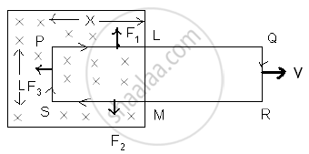
Three forces act on the coil.
F1 on conductor PL ∴ F1 = Bi x, vertically upward.
F2 on conductor MS ∴ F2 = Bi x, vertically downward.
F3 on conductor SP ∴ F3 = Bi L towards left.
F1 and F2 are equal and opposite and also on the same line. They will cancel each other; F3 is a resultant force. The external agent has to do work against this force.
∴ F3 = −Bi l ...(−ve sign indicates that force is opposite to dx.)
If dx is the displacement in time dt, then the work done (dw) = F3 dx.
∴ dw = − BiL dx
This power is an electrical energy ‘ei’ where ‘e’ is an induced e.m.f.
∴ ei = `-(B_i ldx)/(dt)`
∴ e = `-(BLdx)/(dt)`
∴ e = −BLv
∴ e = `-d/dt (BLx)`
∴ e = `(-d phi)/(dt)` ...[from eq (1)]
Lenz’s Law states that the direction of the induced electromotive force (EMF) and the resulting current in a conductor is always such that it opposes the change in magnetic flux that caused it.
Mathematically, Lenz’s Law is expressed as:
ε = `(-d phi_B)/dt`
Where,
ε = Induced EMF
ΦB = Magnetic flux
The negative sign indicates opposition to the change in flux.
Law: Faraday's Second Law or Lenz's Law
Statement:
The direction of the induced emf, or the induced current, in any circuit is such as to oppose the cause that produces it. This law is known as Lenz’s Law.
Explanation / Proof:
- When the north pole of a magnet is moved towards the coil, an induced current flows in the coil in such a direction that the near (left) face of the coil behaves like a north pole.
- Due to the repulsion between the like poles, the motion of the magnet towards the coil is opposed.
- When the north pole of the magnet is moved away from the coil, the induced current flows in such a direction that the near face of the coil becomes a south pole.
- The attraction between opposite poles then opposes the motion of the magnet away from the coil.
In both cases, the induced current opposes the magnet's motion, which is the cause of the current. Therefore, work has to be done to move the magnet, and this mechanical work appears as electrical energy in the coil.
Direction of Induced Current (Fleming’s Right-Hand Rule):
- Stretch the right-hand thumb, forefinger, and middle finger so that they are mutually perpendicular.
- The forefinger points in the direction of the magnetic field.
- The thumb points in the direction of motion of the conductor.
- The middle finger then gives the direction of the induced current.
Conclusion:
Lenz’s Law shows that the induced current always acts in such a direction as to oppose the cause that produces it. This ensures that mechanical energy is converted into electrical energy, and no energy is produced without work being done.
Law: Faraday's First Law or Neumann’s law
Statement:
When the magnetic flux through a circuit is changing, an induced electromotive force (emf) is set up in the circuit whose magnitude is equal to the negative rate of change of magnetic flux. This is also known as Neumann’s Law.
Mathematical Expression:
If ΔΦB is the change in magnetic flux in a time interval Δt, then the induced emf e is given by:
e = \[-\frac{\Delta\Phi_B}{\Delta t}\]
In the limiting case as Δt → 0:
e = \[-\frac{d\Phi_{B}}{dt}\]
- If dΦB is in weber (Wb) and dtdtdt in seconds (s), then the emf eee will be in volts (V).
- This equation represents an independent experimental law, which cannot be derived from other experimental laws.
For a tightly-wound coil of N turns, the induced emf becomes:
e = \[-N\frac{d\Phi_B}{dt}\] or e = \[-\frac{d(N\Phi_B)}{dt}\]
Here, NΦB is called the ‘number of magnetic flux linkages’ in the coil, and its unit is weber-turns.
Explanation:
Consider a magnet and a coil:
- When the north pole of a magnet is near a coil, a certain number of magnetic flux lines pass through the coil.
- If either the coil or the magnet is moved, the number of magnetic flux lines (i.e., the magnetic flux) through the coil changes.
Cases:
- Magnet moved away from the coil → Decrease in magnetic flux through the coil.
- Magnet brought closer to the coil → Increase in magnetic flux through the coil.
In both cases, an emf is induced in the coil during the motion of the magnet.
- Faster motion → Greater rate of change of flux → Higher induced emf.
- If both the magnet and coil are stationary, or both are moving in the same direction with the same velocity, there is no change in flux → No induced emf.
Special Case:
- If the coil is an open circuit (i.e., infinite resistance), emf is still induced, but no current flows.
- This shows that it is the change in magnetic flux that induces emf, not current.
Conclusion:
Neumann’s Law establishes that a changing magnetic flux through a circuit induces an emf, and the induced emf is proportional to the rate of change of flux, with a negative sign indicating the direction (as per Lenz’s law).
Law: Principle of a Transformer
A transformer is based on the principle of mutual induction, i.e., whenever the magnetic flux linked with a coil changes, an emf is induced in the neighbouring coil. For an ideal transformer there is no loss of power, so Pinput = Poutput. On the basis of winding, transformers are of two types — step-up and step-down.
Key Points
Key Points: Magnetic Field Due to a Straight Current-carrying Conductor of Finite Size
- Biot–Savart's Law gives the field due to a current element; integrating over a finite wire gives B = \[\frac {μ_0I}{4πr}\](sin ϕ1 + sin ϕ2).
- For an infinite wire, B = \[\frac {μ_0I}{2πr}\].
- For a semi-infinite wire, B = \[\frac {μ_0I}{4πr}\] (half of infinite wire).
- For a point on the perpendicular bisector of a finite wire of length l, B = \[\frac{\mu_0I}{2\pi r}\cdot\frac{l}{\sqrt{4r^2+l^2}}\].
- The field is always directly proportional to I and inversely proportional to r.
- Direction is found using the right-hand palm rule.
Key Points: Magnetic Field at the Axis of a Circular Current-carrying Loop
- A circular current loop produces a magnetic field whose axial value is B = \[\frac{\mu_0IR^2}{2(x^2+R^2)^{3/2}}\].
- At the centre of the loop (x = 0), this simplifies to B0 = \[\frac {μ_0I}{2R}\], and for N turns, B0 = \[\frac {μ_0NI}{2R}\].
- Perpendicular field components from opposite points on the loop cancel; only axial components add up.
- Direction follows the right-hand thumb rule; one face of the loop acts as a north pole, the other as a south pole.
- Straight wire segments (as in a semicircular arc problem) contribute zero field at a point lying on the line of the wire itself.
Key Points:
- A current-carrying conductor in a magnetic field experiences a force perpendicular to both the current and the field direction.
- Reversing current or reversing field polarity reverses the force direction.
- Formula: F = BIl sin θ; vector form \[\vec F\] = I\[\vec l\] × \[\vec B\].
- Force is zero when the wire is parallel to \[\vec{B}\] and maximum (Fmax = BIl) when perpendicular.
- Fleming's Left-Hand Rule (thumb = force, forefinger = field, middle finger = current) is the standard tool for direction in Indian board exams.
Key Points: Simple D.C. Motor
Key Points: Introduction to Electromagnetic Induction
- Electricity and magnetism are interrelated.
- Electric current can produce a magnetic field.
- A changing magnetic field can produce electric current.
- The production of electric current by a varying magnetic field is called electromagnetic induction.
- Michael Faraday showed in 1831 that a moving magnet can produce current in a conductor.
- The current produced due to electromagnetic induction is called induced current.
- Generators, transformers, induction motors, and wireless chargers work on electromagnetic induction.
Important Questions [21]
- On reversing the direction of the current in a wire, the magnetic field produced by it gets ______.
- Given below is a circuit to study the magnetic effect of electric current. ABCD is a cardboard kept perpendicular to the conductor XY. A magnetic compass is placed at the point P of the cardboard.
- State the Direction in Which Current-carrying Rests
- Why Does a Current Carrying, Freely Suspended Solenoid Rest Along a Particular Direction?
- The diagram shows a coil wound around a U-shaped soft iron bar AB. (1) What is the polarity induced at the ends A and B when the switch is pressed?
- State Any Two Advantages of Electromagnets Over Permanent Magnets.
- State Two Ways to Increase the Speed of Rotation of a D.C. Motor.
- A copper conductor is placed over two stretched copper wires whose ends ate connected to a D.C. supply as shown in the diagram.
- If the strength of the current flowing through a wire is increased, the strength of the magnetic field produced by it ______.
- State two factors affecting the coil's rotation speed in a D.C. motor.
- Name a Common Device that Uses Electromagnets.
- In the Following Diagram an Arrow Shows the Motion of the Coil Towards the Bar Magnet.
- Draw a Neat Labeled Diagram of an A.C. Generator
- State one factor that affects the magnitude of induced current in an AC generator.
- Give two similarities an AC generator and a DC motor
- How is the E.M.F. Across Primary and Secondary Coils of a Transformer Related with the Number of Turns of the Coil in Them?
- Name the Transformer Used in the Power Transmitting Station of a Power Plant.
- What Type of Current is Transmitted from the Power Station?
- Name two factors on which the magnitude of an induced e.m.f. in the secondary coil depends.
- Which Coil of a Step up Transformer is Made Thicker and Why?
- On which type of current do transformers work?
Concepts [20]
- Oersted's Experiment
- Applications of Biot-Savart's Law > Magnetic Field Due to a Straight Current-carrying Conductor of Finite Size
- Right-hand Thumb Rule
- Applications of Biot-Savart's Law > Magnetic Field at the Axis of a Circular Current-carrying Loop
- Applications of Ampere’s Circuital Law > Magnetic Field of a Long Straight Solenoid
- Electromagnet
- Permanent Magnet
- Comparison of an Electro Magnet with a Permanent Magnet
- Advantages of an Electromagnet over a Permanent Magnet
- Uses of Electromagnet
- Force on a Current-Carrying Conductor Placed in a Uniform Magnetic Field
- Simple D.C. Motor
- Introduction to Electromagnetic Induction
- Electromagnetic Induction: Experimental Demonstration
- Faraday's Explanation
- Faraday's Laws of Electromagnetic Induction
- Alternating-Current Generator
- Frequency of an a.c. in Household Supplies
- Comparison Between A.C. Generator and D.C. Motor
- Transformers
