Advertisements
Advertisements
Question
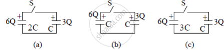
Three circuits, each consisting of a switch 'S' and two capacitors, are initially charged, as shown in the figure. After the switch has been closed, in which circuit will the charge on the left-hand capacitor
(i) increase,
(ii) decrease, and
(iii) remains the same? Give reasons.
Advertisements
Solution
When charged capacitors are connected to each other then the charge will flow from the capacitor with higher potential towards the capacitor with lower potential until a common potential is reached.
(a) In fig. (a) the potential of both the capacitor is same so the charge on left hand capacitor remains the same.
(b) In fig. (b) the potential of left hand capacitor is high so charge from 6Q to 3Q. Therefore charge on left hand capacitor will decrease. (c) In fig.
(c) the potential of left hand capacitor is low so charge will flow from 3Q to 6Q. Therefore charge on the left-hand capacitor will increase.
APPEARS IN
RELATED QUESTIONS
A capacitor has capacitance C. Is this information sufficient to know what maximum charge the capacitor can contain? If yes, what is this charges? If no, what other information is needed?
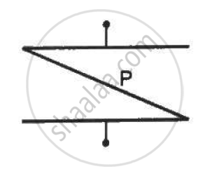
A thin metal plate P is inserted between the plates of a parallel-plate capacitor of capacitance C in such a way that its edges touch the two plates . The capacitance now becomes _________ .
Two metal spheres of capacitance C1 and C2 carry some charges. They are put in contact and then separated. The final charges Q1 and Q2 on them will satisfy
A sphercial capacitor is made of two conducting spherical shells of radii a and b. The space between the shells is filled with a dielectric of dielectric constant K up to a radius c as shown in figure . Calculate the capacitance.

Define ‘capacitance’. Give its unit.
Explain in detail the effect of a dielectric placed in a parallel plate capacitor.
If the plates of a parallel plate capacitor connected to a battery are moved close to each other, then:
- the charge stored in it. increases.
- the energy stored in it, decreases.
- its capacitance increases.
- the ratio of charge to its potential remains the same.
- the product of charge and voltage increases.
Choose the most appropriate answer from the options given below:
Which system is called a capacitor?
What is the SI unit of capacitance?
In a series combination, which statement describes the potential difference across each capacitor?
