Advertisements
Advertisements
Question
In the given circuit, assuming point A to be at zero potential, use Kirchhoff’s rules to determine the potential at point B.

Advertisements
Solution
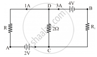
According to Kirchhoff’s Junction Law, when applied at junction D:
Incoming current = outgoing current
So, 3A = 1A + current through 2Ω.
Hence, current through 2Ω is 2A from D to C. Applying Kirchhoff’s law to the loop containing R1, 2Ω and 4V.
3A is the current through R1 as the current coming out from the 4V battery is 3A.
4 = 3 × R1 + 2 × 2
⇒ R1 = 0 Ω
So, no potential drop between B and C.
Now lets analyse the bigger loop containing 4V, R and 2V (R1 can be omitted now); here the 4V and 2V are connected in series with B as a point between the two batteries. So we finally have the potential at B to be 2V.
APPEARS IN
RELATED QUESTIONS
State the two Kirchhoff’s rules used in electric networks. How are there rules justified?
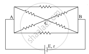
The current is drawn from a cell of emf E and internal resistance r connected to the network of resistors each of resistance r as shown in the figure. Obtain the expression for
- the current draw from the cell and
- the power consumed in the network.
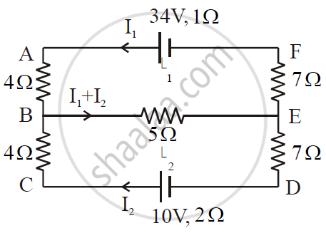
ε1 and ε2 are two batteries having emf of 34V and 10V respectively and internal resistance of 1Ω and 2Ω respectively. They are connected as shown in the figure below. Using Kirchhoff’s Laws of electrical networks, calculate the currents I1 and I2.
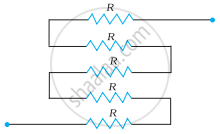
Determine the equivalent resistance of networks shown in Fig.
Consider the potentiometer circuit as arranged in the figure. The potentiometer wire is 600 cm long. (a) At what distance from the point A should the jockey touch the wire to get zero deflection in the galvanometer? (b) If the jockey touches the wire at a distance of 560 cm from A, what will be the current in the galvanometer?
The Kirchhoff's second law (ΣiR = ΣE), where the symbols have their usual meanings, is based on ______.
Kirchhoff s second law is based on the law of conservation of ______
Three resistors having resistances r1, r2 and r3 are connected as shown in the given circuit. The ratio `i_3/i_1` of currents in terms of resistances used in the circuit is:
Why are alloys used for making standard resistance coils?
The figure below shows two batteries, E1 and E2, having emfs of 18V and 10V and internal resistances of 1 Ω and 2 Ω, respectively. W1, W2 and W3 are uniform metallic wires AC, FD and BE having resistances of 8 Ω, 6 Ω and 10 Ω respectively. B and E are midpoints of the wires W1 and W2. Using Kirchhoff's laws of electrical circuits, calculate the current flowing in the wire W3:

