Advertisements
Advertisements
Question
(i) Draw a clear labelled diagram of an electric bell.
(ii) Explain in brief, its working.
(iii) What material is used for the core of an electric bell? State the reason.
Advertisements
Solution
(i)

(ii) An electric bell is one of the most common applications of an electromagnet.
Construction and wiring: An electric bell shown in above fig. The main parts of the bell are:
- A horse-shoe electromagnet M, having iron core,
- Soft iron armature A,
- A hammer H,
- A gong G,
- A metallic spring strip SS,
- An adjusting screw SS,
- A switch (or bell-push) K, and
- A battery.
Working and function of each part:
The working of an electric bell is based on the magnetic effect of current. When the electric circuit is closed by pressing the switch K, the current flows through the coil CC and the core of electromagnet gets magnetized and therefore it attracts the armature A as shown A, the hammer H strikes the gong G and the bell rings.
At the moment, when the armature, due to attraction, moves towards the electromagnet, the connection between the strip SS and the screw S’ breaks which stops the flow of current in the circuit. Consequently, the electromagnet loses magnetism (i.e.r it gets demagnetized) and the armature A flies back to its original position due to the spring effect of the strip SS. Now the armature again touches the screw S’, resulting in the flow of current in the circuit. The electromagnet regains its magnetism and the armature A is again attracted, so the hammer H strikes the gong G again.
This process of make and break of the circuit goes on the hammer strikes the gong repeatedly and the bell rings so long as the switch K is kept pressed.
(iii) The core of the electromagnet is made of soft iron because: Firstly, it increases the intensity of the magnetic field of the electromagnet and secondly it easily get demagnetized when no current flows in the turns of the coil of insulated copper wire wound over the core, thus helping in the smooth working of the electric bell.
RELATED QUESTIONS
You are required to make an electromagnet from a soft iron bar by using a cell, an insulated coil of copper wire and a switch. (a) Draw a circuit diagram to represent the process. (b) label the poles of the electromagnet.
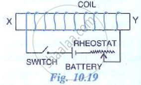
The adjacent diagram shows a coil would around a soft iron bar XY. (a) State the polarity at the end X and Y as the switch is pressed. (b) Suggest one way increasing the strength of electromagnet so formed.
Name two kind of energy loss in a transformer. How is it minimized?
The power supply to the primary coil of a transformer is 200 W. Find
(i) Current in primary coil if the e.m.f. supply to it is equal to 220V.
(ii) The number of turns in the primary coil is equal to 80 and that in secondary is 800. What is the transformation ratio?
(iii) Name the type of transformer.
(iv) What will be the output voltage?
(v) What is the current in the secondary coil for an ideal transformer?
(vi) What is the output power?
(vii) Is output and input power equal?
(viii) Compare the current flowing in a secondary coil and in a primary coil.
A 220 V input is supplied to a transformer. The output circuit draws a current of 2.0 A at 440 V. If the ratio of output to input power is 0.8, then the current drawn by primary winding is ______.
Read the following paragraph and answer the question:

Long distance power transmissions
The large-scale transmission and distribution of electrical energy over long distances is done with the use of transformers. The voltage output of the generator is stepped up. It is then transmitted over long distances to an area sub-station near the consumers. There the voltage is stepped down. It is further stepped down at distributing sub-stations and utility poles before a power supply of 240 V reaches our homes.
A power transmission line feeds input power at 2300 V to a step down transformer with its primary windings having 4000 turns. The number of turns in the secondary in order to get output power at 230 V are ______.
An ideal transformer converts 220 V a.c. to 3.3 kV a.c. to transmit a power of 4.4 kW. If primary coil has 600 turns, then alternating current in secondary coil is ______.
Mention two main sources of power loss in real transformers.
What is a transformer?
An ideal transformer converts 170 V a.c. to 1.70 KV a.c. to transmit a power of 3.4 KW. If primary coil has 500 turns then alternating current in secondary coil is ______.
