Advertisements
Advertisements
प्रश्न
(i) Draw a clear labelled diagram of an electric bell.
(ii) Explain in brief, its working.
(iii) What material is used for the core of an electric bell? State the reason.
Advertisements
उत्तर
(i)

(ii) An electric bell is one of the most common applications of an electromagnet.
Construction and wiring: An electric bell shown in above fig. The main parts of the bell are:
- A horse-shoe electromagnet M, having iron core,
- Soft iron armature A,
- A hammer H,
- A gong G,
- A metallic spring strip SS,
- An adjusting screw SS,
- A switch (or bell-push) K, and
- A battery.
Working and function of each part:
The working of an electric bell is based on the magnetic effect of current. When the electric circuit is closed by pressing the switch K, the current flows through the coil CC and the core of electromagnet gets magnetized and therefore it attracts the armature A as shown A, the hammer H strikes the gong G and the bell rings.
At the moment, when the armature, due to attraction, moves towards the electromagnet, the connection between the strip SS and the screw S’ breaks which stops the flow of current in the circuit. Consequently, the electromagnet loses magnetism (i.e.r it gets demagnetized) and the armature A flies back to its original position due to the spring effect of the strip SS. Now the armature again touches the screw S’, resulting in the flow of current in the circuit. The electromagnet regains its magnetism and the armature A is again attracted, so the hammer H strikes the gong G again.
This process of make and break of the circuit goes on the hammer strikes the gong repeatedly and the bell rings so long as the switch K is kept pressed.
(iii) The core of the electromagnet is made of soft iron because: Firstly, it increases the intensity of the magnetic field of the electromagnet and secondly it easily get demagnetized when no current flows in the turns of the coil of insulated copper wire wound over the core, thus helping in the smooth working of the electric bell.
संबंधित प्रश्न
On which type of current do transformers work?
The following diagram in Fig. 10.44 shows a coil X connected to a sensitive centre –zero galvanometer G and a coil P connected to a battery through a switch S.
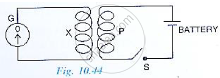
(a) Describe the observation when the switch S is (i) closed suddenly, (ii) then kept closed, (iii) finally opened.
(b) Name and state the law which explains the above observations.
Why is the iron core of a transformer made laminated (thin sheets) instead of being in one solid piece?
What is a transformer? On what principle does it work?
Can a transformer be used with direct current source? Give reason.
What is the function of a step-up transformer?
In a transformer, the number of turns in the primary and the secondary are 410 and 1230 respectively. If the current in primary is 6A, then that in the secondary coil is
Assertion: A transfonner cannot work on D.C. supply.
Reason: D.C. changes neither in magnitude nor in direction.
A transformer works on the principle of ______.
For an LCR circuit, the power transferred from the driving source to the driven oscillator is P = I2Z cos φ.
- Here, the power factor cos φ ≥ 0, P ≥ 0.
- The driving force can give no energy to the oscillator (P = 0) in some cases.
- The driving force cannot syphon out (P < 0) the energy out of oscillator.
- The driving force can take away energy out of the oscillator.
