Advertisements
Advertisements
Question
How the emf of two cells are compared using potentiometer?
Advertisements
Solution
To compare the emf of two cells, the circuit connections are made as shown in figure. Potentiometer wire CD is connected to a battery Bt and a key K in series. This is the primary circuit. The end C of the wire is connected to the terminal M of a DPDT (Double Pole Double Throw) switch and the other terminal N is connected to a jockey through a galvanometer G and a high resistance HR. The cells whose emf ξ1 and ξ2 to be compared are connected to the terminals M1, N1 and M2, N2 of the DPDT switch.

Potentiometer
The positive terminals of Bt, ξ1 and ξ2 should be connected to the same end C. The DPDT switch is pressed towards M1, N1 so that cell ξ1 is included in the secondary circuit and the balancing length l1 is found by adjusting the jockey for zero deflection, Then the second cells ξ2 is included in the circuit and the balancing length l2 is determined. Let r be the resistance per unit length of the potentiometer wire and I be the current flowing through the wire.
we have.
ξ1 = Irl1 …… (1)
ξ2 = Irl2 ……. (2)
By dividing (1) by (2)
`ξ^1/ξ^2 = l^1/l^2` .....(3)
By including a rheostat (Rh) in the primary circuit, the experiment can be repeated several times by changing the current flowing through it.
APPEARS IN
RELATED QUESTIONS
Calculate the value of the resistance R in the circuit shown in the figure so that the current in the circuit is 0.2 A. What would b the potential difference between points A and B?

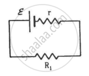
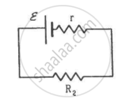
Two unequal resistances, R1 and R2, are connected across two identical batteries of emf ε and internal resistance r (see the figure). Can the thermal energies developed in R1 and R2 be equal in a given time? If yes, what will be the condition?
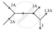
The figure below shows current in a part of electric circuit. The current I is ______.
What is the advantage of using thick metallic strips to join wires in a potentiometer?
Power P is to be delivered to a device via transmission cables having resistance RC. If V is the voltage across R and I the current through it, find the power wasted and how can it be reduced.
In the circuit shown in Figure below, E1 and E2 are batteries having emfs of 25V and 26V. They have an internal resistance of 1 Ω and 5 Ω respectively. Applying Kirchhoff’s laws of electrical networks, calculate the currents I1 and I2.

Which two basic physical principles form the basis of Kirchhoff's laws?
What is Kirchhoff's Current Law also called?
What is Kirchhoff's Voltage Law also called?
What does Kirchhoff's Voltage Law state for a closed loop?
