Advertisements
Advertisements
प्रश्न
How the emf of two cells are compared using potentiometer?
Advertisements
उत्तर
To compare the emf of two cells, the circuit connections are made as shown in figure. Potentiometer wire CD is connected to a battery Bt and a key K in series. This is the primary circuit. The end C of the wire is connected to the terminal M of a DPDT (Double Pole Double Throw) switch and the other terminal N is connected to a jockey through a galvanometer G and a high resistance HR. The cells whose emf ξ1 and ξ2 to be compared are connected to the terminals M1, N1 and M2, N2 of the DPDT switch.

Potentiometer
The positive terminals of Bt, ξ1 and ξ2 should be connected to the same end C. The DPDT switch is pressed towards M1, N1 so that cell ξ1 is included in the secondary circuit and the balancing length l1 is found by adjusting the jockey for zero deflection, Then the second cells ξ2 is included in the circuit and the balancing length l2 is determined. Let r be the resistance per unit length of the potentiometer wire and I be the current flowing through the wire.
we have.
ξ1 = Irl1 …… (1)
ξ2 = Irl2 ……. (2)
By dividing (1) by (2)
`ξ^1/ξ^2 = l^1/l^2` .....(3)
By including a rheostat (Rh) in the primary circuit, the experiment can be repeated several times by changing the current flowing through it.
APPEARS IN
संबंधित प्रश्न
Kirchhoff's voltage law and current law are respectively in accordance with the conservation of .................................. .
- charge and momentum
- charge and energy
- energy and charge
- energy and momentum
State the two Kirchhoff’s rules used in electric networks. How are there rules justified?
Use Kirchhoff's rules to obtain conditions for the balance condition in a Wheatstone bridge.
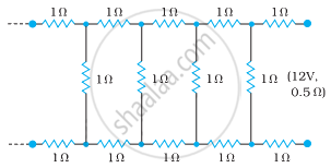
Determine the current drawn from a 12 V supply with internal resistance 0.5 Ω by the infinite network shown in the figure. Each resistor has 1 Ω resistance.
State Kirchhoff's rules and explain on what basis they are justified.
Given the resistances of 1 Ω, 2 Ω, 3 Ω, how will be combine them to get an equivalent resistance of (11/5) Ω?
Given the resistances of 1 Ω, 2 Ω, 3 Ω, how will be combine them to get an equivalent resistance of (6/11) Ω?
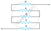
Determine the equivalent resistance of networks shown in Fig.
Kirchhoff’s junction rule is a reflection of ______.
- conservation of current density vector.
- conservation of charge.
- the fact that the momentum with which a charged particle approaches a junction is unchanged (as a vector) as the charged particle leaves the junction.
- the fact that there is no accumulation of charges at a junction.
A 6-volt battery is connected to the terminals of a three-metre-long wire of uniform thickness and resistance of 100 ohms. The difference of potential between two points on the wire separated by a distance of 50 cm will be ______.
