Advertisements
Advertisements
Question
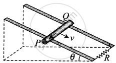
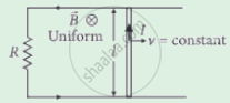
A rod of mass m and resistance R slides smoothly over two parallel perfectly conducting wires kept sloping at an angle θ with respect to the horizontal (Figure). The circuit is closed through a perfect conductor at the top. There is a constant magnetic field B along the vertical direction. If the rod is initially at rest, find the velocity of the rod as a function of time.

Advertisements
Solution
Let us first divide the magnetic field in the components one is along the inclined plane = B sin θ and other component of magnetic field is perpendicular the plane = B cos θ
Now, the conductor moves with speed v perpendicular to B cos θ, component of magnetic field. This causes motional emf across two ends of rod, which is given by = v(B cos θ)d
 (A) |
 (B) |
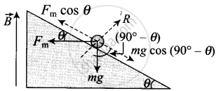
This makes flow of induced current `i = (v(B cos theta)d)/R` where R is the resistance of rod. Now, current carrying rod experience a magnetic force which is given by `F_m = iBd` (horizontally in backwards direction). Now, the component of magnetic force parallel to the inclined plane in upward direction
`F_(||) = F_m cos θ = -Bd cos θ = ((v(B cos θ)d)/R) Bd cos θ`
Where, `v = (dx)/(dt)`
Also, the component of weight (mg) parallel to the inclined plane along downward direction = mg sin θ.
Now, by Newton's second law of motion
`m (d^2x)/(dl^2) = mg sin θ - (B cos θ d)/R ((dx)/(dt)) xx (Bd) cos θ`
⇒ `(dv)/(dt) = g sin θ - (B^2d^2)/(mR) (cos theta)^2v`
⇒ `(dv)/(dt) + (B^2d^2)/(mR) (cos θ)^2v = g sin θ`
But, this is the linear differential equation.
On solving, we get
`v = ((g sin θ)/(B^2d^2 cos^2 θ))/(mR) + A exp(- (B^2d^2)/(mR) (cos^2 θ)t)`
A is a constant to be determined by initial conditions.
The required expression of velocity as a function of time is given by
= `(mgR sin θ)/(B^2d^2 cos^2θ) (1 - exp (- (B^2d^2)/(mR) (cos^2θ)t))`
APPEARS IN
RELATED QUESTIONS
A conducting disc of radius r rotates with a small but constant angular velocity ω about its axis. A uniform magnetic field B exists parallel to the axis of rotation. Find the motional emf between the centre and the periphery of the disc.
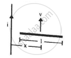
Figure shows a straight, long wire carrying a current i and a rod of length l coplanar with the wire and perpendicular to it. The rod moves with a constant velocity v in a direction parallel to the wire. The distance of the wire from the centre of the rod is x. Find the motional emf induced in the rod.
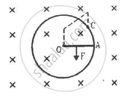
Consider the situation shown in the figure. Suppose the wire connecting O and C has zero resistance but the circular loop has a resistance Runiformly distributed along its length. The rod OA is made to rotate with a uniform angular speed ω as shown in the figure. Find the current in the rod when ∠ AOC = 90°.
Mechanical force per unit area of a charged conductor is ______
A cycle wheel of radius 0.6 m is rotated with constant angular velocity of 15 rad/s in a region of magnetic field of 0.2 T which is perpendicular to the plane of the wheel. The e.m.f generated between its center and the rim is, ____________.
A wire of length 50 cm moves with a velocity of 300 m/min, perpendicular to a magnetic field. If the e.m.f. induced in the wire is 2 V, the magnitude of the field in tesla is ______.
The emf induced across the ends of a conductor due to its motion in a magnetic field is called motional emf. It is produced due to magnetic Lorentz force acting on the free electrons of the conductor. For a circuit shown in the figure, if a conductor of length l moves with velocity v in a magnetic field B perpendicular to both its length and the direction of the magnetic field, then all the induced parameters are possible in the circuit.
Direction of current induced in a wire moving in a magnetic field is found using ______.
Motional e.m.f is the induced e.m.f. ______
An e.m.f is produced in a coil, which is not connected to an external voltage source. This can be due to ______.
- the coil being in a time varying magnetic field.
- the coil moving in a time varying magnetic field.
- the coil moving in a constant magnetic field.
- the coil is stationary in external spatially varying magnetic field, which does not change with time.
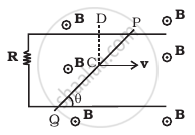
Find the current in the wire for the configuration shown in figure. Wire PQ has negligible resistance. B, the magnetic field is coming out of the paper. θ is a fixed angle made by PQ travelling smoothly over two conducting parallel wires separated by a distance d.
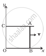
A magnetic field B = Bo sin ( ωt )`hatk` wire AB slides smoothly over two parallel conductors separated by a distance d (Figure). The wires are in the x-y plane. The wire AB (of length d) has resistance R and the parallel wires have negligible resistance. If AB is moving with velocity v, what is the current in the circuit. What is the force needed to keep the wire moving at constant velocity?
An aeroplane, with its wings spread 10 m, is flying at a speed of 180 km/h in a horizontal direction. The total intensity of earth's field at that part is 2.5 × 10⁻⁴ Wb/m2 and the angle of dip is 60°. The emf induced between the tips of the plane wings will be ______.
A simple pendulum with a bob of mass m and conducting wire of length L swings under gravity through an angle θ. The component of the earth's magnetic field in the direction perpendicular to the swing is B. Maximum emf induced across the pendulum is ______.
(g = acceleration due to gravity)

A wire 5 m long is supported horizontally at a height of 15 m along an east-west direction. When it is about to hit the ground, calculate the average e.m.f. induced in it. (g = 10 m/s2)
Derive an expression for the total emf induced in a conducting rotating rod.
A magnetic flux associated with a coil changes by 0.04 Wb in 0.2 second. The induced emf with coil is ______.
An aircraft of wing span of 60 m flies horizontally in earth’s magnetic field of 6 × 10⁻⁵ T at a speed of 500 m/s. Calculate the e.m.f. induced between the tips of the wings of the aircraft.
