Advertisements
Advertisements
Question
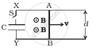
Find the current in the sliding rod AB (resistance = R) for the arrangement shown in figure. B is constant and is out of the paper. Parallel wires have no resistance. v is constant. Switch S is closed at time t = 0.
Advertisements
Solution
This is a similar problem as we discussed above. Here, a conductor of length d moves with speed v, perpendicular to the magnetic field B as shown in figure.
Due to this a motional emf is induced across two ends of rod (e = vBd). Since switch S is closed at time t = 0, capacitor is charged by this potential difference.
Let Q(t) be the charge on the capacitor and current flows from A to B.
Now, the induced current
`I = (dQ)/(dt) = (Bvd) - Q/(RC)`
`Q/(RC) + (dQ)/(dt) = (Bvd)/R`
`Q + RC (dQ)/(dt) = vBC` .....(Let `vBdC = A`)
`Q + RC Q/(dt) A`
`(dQ)/(A - Q) = 1/(RC) dt`
By integrating we have
`int_0^Q (dQ)/(A - Q) = 1/(RC) int_0^t dt - [In (A -Q) - In A] = t/(RC)`
In ``(A / Q)/A = - t/(RC)`
`(A - Q)/A = e^(-t/(RC))`
`Q = A(1 - e^(-t/(RC)))`
Current in the rod,
`I = (dQ)/(dt) = d/(dt) [A(1 - e^(-t/(RC)))]`
= `- A(e^-t/(RC))(- 1/(RC))`
`I = (vBd)/R e^(-t/(RC)`
APPEARS IN
RELATED QUESTIONS
A conducting disc of radius r rotates with a small but constant angular velocity ω about its axis. A uniform magnetic field B exists parallel to the axis of rotation. Find the motional emf between the centre and the periphery of the disc.
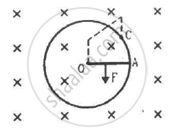
Consider the situation shown in the figure. Suppose the wire connecting O and C has zero resistance but the circular loop has a resistance Runiformly distributed along its length. The rod OA is made to rotate with a uniform angular speed ω as shown in the figure. Find the current in the rod when ∠ AOC = 90°.
An aircraft of wing span of 50 m flies horizontally in the Earth's magnetic field of 6 x 10⁻⁵ T at a speed of 400 m/s. Calculate the emf generated between the tips of the wings of the aircraft.
Mechanical force per unit area of a charged conductor is ______
A straight conductor of length 2 m moves in a uniform magnetic field of induction 2.5 x `10^-3` T with a velocity. of 4 m/s in a direction perpendicular to its length and also perpendicular to the field. The e.m.f. induced between the ends of the conductor is ______.
A wire of length 50 cm moves with a velocity of 300 m/min, perpendicular to a magnetic field. If the e.m.f. induced in the wire is 2 V, the magnitude of the field in tesla is ______.
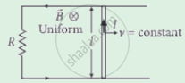
The emf induced across the ends of a conductor due to its motion in a magnetic field is called motional emf. It is produced due to magnetic Lorentz force acting on the free electrons of the conductor. For a circuit shown in the figure, if a conductor of length l moves with velocity v in a magnetic field B perpendicular to both its length and the direction of the magnetic field, then all the induced parameters are possible in the circuit.
Direction of current induced in a wire moving in a magnetic field is found using ______.
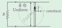
The emf induced across the ends of a conductor due to its motion in a magnetic field is called motional emf. It is produced due to magnetic Lorentz force acting on the free electrons of the conductor. For a circuit shown in the figure, if a conductor of length l moves with velocity v in a magnetic field B perpendicular to both its length and the direction of the magnetic field, then all the induced parameters are possible in the circuit.
A bicycle generator creates 1.5 V at 15 km/hr. The EMF generated at 10 km/hr is ______.
Motional e.m.f is the induced e.m.f. ______
A magnetic field B = Bo sin ( ωt )`hatk` wire AB slides smoothly over two parallel conductors separated by a distance d (Figure). The wires are in the x-y plane. The wire AB (of length d) has resistance R and the parallel wires have negligible resistance. If AB is moving with velocity v, what is the current in the circuit. What is the force needed to keep the wire moving at constant velocity?
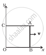
A rod of mass m and resistance R slides smoothly over two parallel perfectly conducting wires kept sloping at an angle θ with respect to the horizontal (Figure). The circuit is closed through a perfect conductor at the top. There is a constant magnetic field B along the vertical direction. If the rod is initially at rest, find the velocity of the rod as a function of time.

A simple pendulum with a bob of mass m and conducting wire of length L swings under gravity through an angle θ. The component of the earth's magnetic field in the direction perpendicular to the swing is B. Maximum emf induced across the pendulum is ______.
(g = acceleration due to gravity)

An aircraft of wing span of 60 m flies horizontally in earth’s magnetic field of 6 × 10⁻⁵ T at a speed of 500 m/s. Calculate the e.m.f. induced between the tips of the wings of the aircraft.
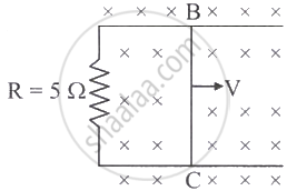
Figure shows a rectangular frame situated in a constant magnetic field. A wire BC of length 1 m is moved out with velocity 4 m/s. Magnetic field strength is 0.15 T. Force acting on the wire BC is:
If a rod moves a distance \[dx\] in time \[dt\], what is the change in magnetic flux used in the Faraday's Law derivation?
What Lorentz force does each free electron in the moving rod experience when \[\vec{v}\perp\vec{B}\]?
For a rotating rod, what is the velocity of a small element at distance \[r\] from the centre?
What is the motional EMF across a small element \[dr\] of a rotating rod?
A metallic rod rotates at \[50\,\mathrm{rev/s}\]. What is its angular velocity?
