Advertisements
Advertisements
Question
A conductor of length ‘l’ is rotated about one of its ends at a constant angular speed ‘ω’ in a plane perpendicular to a uniform magnetic field B. Plot graphs to show variations of the emf induced across the ends of the conductor with
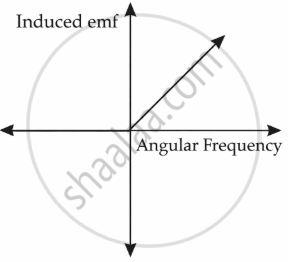
- angular speed ω and
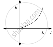
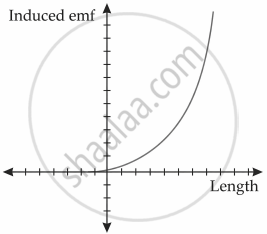
- length of the conductor l.
Advertisements
Solution 1
Induced emf (E) = `(B omega l^2)/2`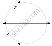
Solution 2
i. e = `1/2 B omega L^2`
So, e ∝ ω
ii. e = `1/2 B omega L^2`
So, e ∝ L2
RELATED QUESTIONS
The plot of the variation of potential difference across a combination of three identical cells in series, versus current is shown below. What is the emf and internal resistance of each cell ?
A potentiometer wire of length 1.0 m has a resistance of 15 Ω. It is connected to a 5 V battery in series with a resistance of 5 Ω. Determine the emf of the primary cell which gives a balance point at 60 cm.
Two identical cells, each of emf E, having negligible internal resistance, are connected in parallel with each other across an external resistance R. What is the current through this resistance?
Two non-ideal batteries are connected in series. Consider the following statements:-
(A) The equivalent emf is larger than either of the two emfs.
(B) The equivalent internal resistance is smaller than either of the two internal resistances.
A plate of area 10 cm2 is to be electroplated with copper (density 9000 kg m−3) to a thickness of 10 micrometres on both sides, using a cell of 12 V. Calculate the energy spent by the cell in the process of deposition. If this energy is used to heat 100 g of water, calculate the rise in the temperature of the water. ECE of copper = 3 × 10⁻⁷ kg C−1and specific heat capacity of water = 4200 J kg−1.
A cell having an emf E and internal resistance r is connected across a variable external resistance R. As the resistance R is increased, the plot of potential difference V across R is given by ______.
If n cells each of emf e and internal resistance r are connected in parallel, then the total emf and internal resistance will be ______.
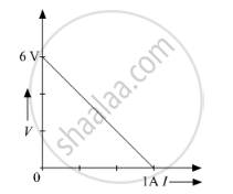
A straight line plot showing the terminal potential difference (V) of a cell as a function of current (I) drawn from it, is shown in the figure. The internal resistance of the cell would be then ______.

Study the two circuits shown in the figure below. The cells in the two circuits are identical to each other. The resistance of the load resistor R is the same in both circuits.

If the same current flows through the resistor R in both circuits, calculate the internal resistance of each cell in terms of the resistance of resistor R. Show your calculations.
