Advertisements
Advertisements
प्रश्न
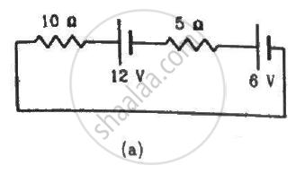
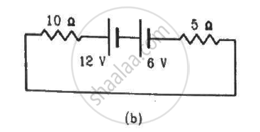
Consider the circuit shown in the figure. Find (a) the current in the circuit (b) the potential drop across the 5 Ω resistor (c) the potential drop across the 10 Ω resistor (d) Answer the parts (a), (b) and (c) with reference to the figure.
Advertisements
उत्तर
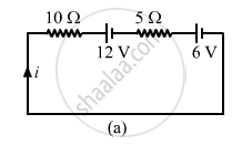
(a)
Applying KVL in the above loop, we get:-
\[10i + 6 + 5i + 12 = 0\]
\[ \Rightarrow 10i + 5i = - 18\]
\[ \Rightarrow 15i = - 18\]
\[ \Rightarrow i = - \frac{18}{15} = - \frac{6}{5} = - 1 . 2 A\]
The negative sign indicates that current is flowing in the direction opposite to our assumed direction.
(b) Potential drop across the 5 Ω resistor= 5i = 5×(-1.2 ) = -6 V
(c) Potential drop across the 10 Ω resistor = 10i = (-1.2) × 10 = 12 V
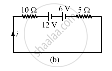
(d)
Applying KVL in the above loop, we get:-
\[10i + 5i + 6 + 12 = 0\]
\[ \Rightarrow 15i = - 18\]
\[ \Rightarrow i = - 1 . 2 A\]
Potential drop across the 5Ω register = -6 V
Potential drop across the 10Ω register = -12 V
APPEARS IN
संबंधित प्रश्न
Kirchhoff's voltage law and current law are respectively in accordance with the conservation of .................................. .
- charge and momentum
- charge and energy
- energy and charge
- energy and momentum
Kirchhoff's junction law is equivalent to .............................
(a) conservation of energy.
(b) conservation of charge
(c) conservation of electric potential
(d) conservation of electric flux
Given n resistors each of resistance R, how will you combine them to get the (i) maximum (ii) minimum effective resistance? What is the ratio of the maximum to minimum resistance?
State Kirchhoff's rules and explain on what basis they are justified.
Given the resistances of 1 Ω, 2 Ω, 3 Ω, how will be combine them to get an equivalent resistance of (11/3) Ω?
Given the resistances of 1 Ω, 2 Ω, 3 Ω, how will be combine them to get an equivalent resistance of 6 Ω?
Given the resistances of 1 Ω, 2 Ω, 3 Ω, how will be combine them to get an equivalent resistance of (6/11) Ω?
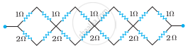
Determine the equivalent resistance of networks shown in Fig.
State Kirchhoff's rules for an electric network. Using Kirchhoff's rules, obtain the balance condition in terms of the resistances of four arms of Wheatstone bridge.
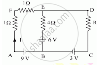
Using Kirchhoff’s rules determine the value of unknown resistance R in the circuit so that no current flows through 4 Ω resistance. Also find the potential difference between A and D.
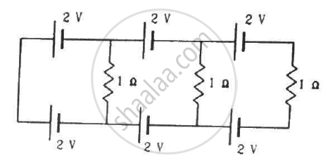
Find the circuit in the three resistors shown in the figure.
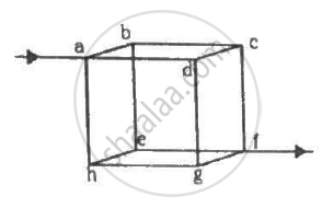
Twelve wires, each of equal resistance r, are joined to form a cube, as shown in the figure. Find the equivalent resistance between the diagonally-opposite points a and f.
A capacitor of capacitance 8.0 μF is connected to a battery of emf 6.0 V through a resistance of 24 Ω. Find the current in the circuit (a) just after the connections are made and (b) one time constant after the connections are made.
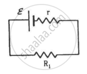
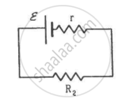
Two unequal resistances, R1 and R2, are connected across two identical batteries of emf ε and internal resistance r (see the figure). Can the thermal energies developed in R1 and R2 be equal in a given time? If yes, what will be the condition?
On which conservation principle is Kirchoff's Second Law of electrical networks based?
Twelve wires each having a resistance of 3 Ω are connected to form a cubical network. A battery of 10 V and negligible internal resistance is connected across the diagonally opposite corners of this network. Determine its equivalent resistance and the current along each edge of the cube.
State Kirchhoff ’s voltage rule.
Obtain the condition for bridge balance in Wheatstone’s bridge.
Explain the determination of unknown resistance using meter bridge.
A copper wire of 10-6 m2 area of cross-section, carries a current of 2 A. If the number of electrons per cubic meter is 8 × 1028, calculate the current density and average drift velocity.
The instrument for the accurate measurement of the e.m.f of a cell is ______.
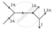
The figure below shows current in a part of electric circuit. The current I is ______.
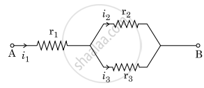
Three resistors having resistances r1, r2 and r3 are connected as shown in the given circuit. The ratio `i_3/i_1` of currents in terms of resistances used in the circuit is:
Three resistors having resistances r1, r2 and r3 are connected as shown in the given circuit. The ratio `"i"_3/"i"_1` of currents in terms of resistances used in the circuit is :
In a meter bridge the point D is a neutral point (Figure).
- The meter bridge can have no other neutral point for this set of resistances.
- When the jockey contacts a point on meter wire left of D, current flows to B from the wire.
- When the jockey contacts a point on the meter wire to the right of D, current flows from B to the wire through galvanometer.
- When R is increased, the neutral point shifts to left.
Why are alloys used for making standard resistance coils?
Power P is to be delivered to a device via transmission cables having resistance RC. If V is the voltage across R and I the current through it, find the power wasted and how can it be reduced.
Derive the equation of the balanced state in a Wheatstone bridge using Kirchhoff’s laws.
A 6-volt battery is connected to the terminals of a three-metre-long wire of uniform thickness and resistance of 100 ohms. The difference of potential between two points on the wire separated by a distance of 50 cm will be ______.
In the circuit shown in Figure below, E1 and E2 are batteries having emfs of 25V and 26V. They have an internal resistance of 1 Ω and 5 Ω respectively. Applying Kirchhoff’s laws of electrical networks, calculate the currents I1 and I2.

