Advertisements
Advertisements
प्रश्न
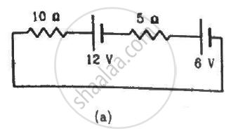
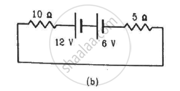
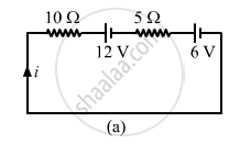
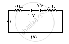
Consider the circuit shown in the figure. Find (a) the current in the circuit (b) the potential drop across the 5 Ω resistor (c) the potential drop across the 10 Ω resistor (d) Answer the parts (a), (b) and (c) with reference to the figure.
Advertisements
उत्तर
(a)
Applying KVL in the above loop, we get:-
\[10i + 6 + 5i + 12 = 0\]
\[ \Rightarrow 10i + 5i = - 18\]
\[ \Rightarrow 15i = - 18\]
\[ \Rightarrow i = - \frac{18}{15} = - \frac{6}{5} = - 1 . 2 A\]
The negative sign indicates that current is flowing in the direction opposite to our assumed direction.
(b) Potential drop across the 5 Ω resistor= 5i = 5×(-1.2 ) = -6 V
(c) Potential drop across the 10 Ω resistor = 10i = (-1.2) × 10 = 12 V
(d)
Applying KVL in the above loop, we get:-
\[10i + 5i + 6 + 12 = 0\]
\[ \Rightarrow 15i = - 18\]
\[ \Rightarrow i = - 1 . 2 A\]
Potential drop across the 5Ω register = -6 V
Potential drop across the 10Ω register = -12 V
APPEARS IN
संबंधित प्रश्न
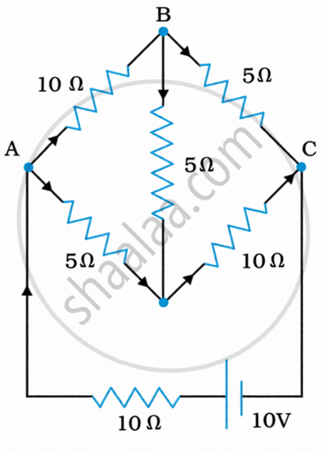
Determine the current in each branch of the network shown in figure.
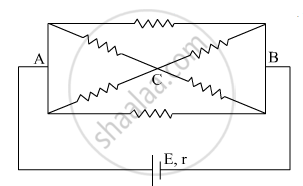
The current is drawn from a cell of emf E and internal resistance r connected to the network of resistors each of resistance r as shown in the figure. Obtain the expression for
- the current draw from the cell and
- the power consumed in the network.
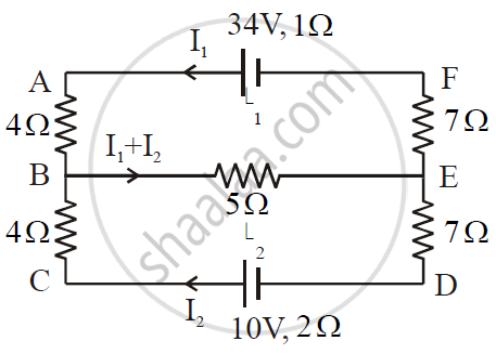
ε1 and ε2 are two batteries having emf of 34V and 10V respectively and internal resistance of 1Ω and 2Ω respectively. They are connected as shown in the figure below. Using Kirchhoff’s Laws of electrical networks, calculate the currents I1 and I2.
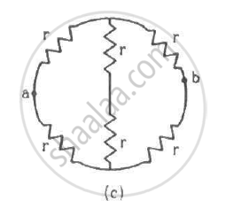
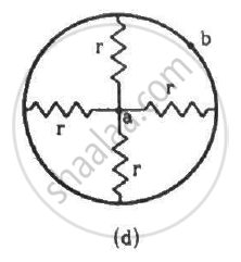
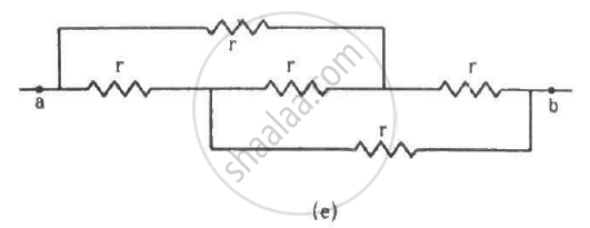
Determine the equivalent resistance of networks shown in Fig.
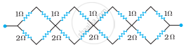
Determine the equivalent resistance of networks shown in Fig.
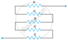
State Kirchhoff's rules for an electric network. Using Kirchhoff's rules, obtain the balance condition in terms of the resistances of four arms of Wheatstone bridge.
Calculate the value of the resistance R in the circuit shown in the figure so that the current in the circuit is 0.2 A. What would b the potential difference between points A and B?

In the given circuit, assuming point A to be at zero potential, use Kirchhoff’s rules to determine the potential at point B.

Find the circuit in the three resistors shown in the figure.
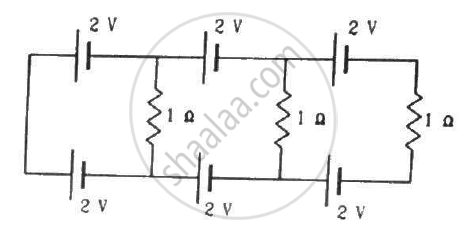
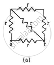
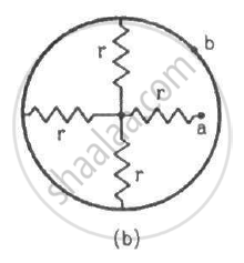
Find the equivalent resistances of the networks shown in the figure between the points a and b.
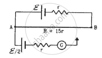
Consider the potentiometer circuit as arranged in the figure. The potentiometer wire is 600 cm long. (a) At what distance from the point A should the jockey touch the wire to get zero deflection in the galvanometer? (b) If the jockey touches the wire at a distance of 560 cm from A, what will be the current in the galvanometer?
A capacitor of capacitance 8.0 μF is connected to a battery of emf 6.0 V through a resistance of 24 Ω. Find the current in the circuit (a) just after the connections are made and (b) one time constant after the connections are made.
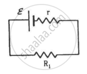
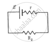
Two unequal resistances, R1 and R2, are connected across two identical batteries of emf ε and internal resistance r (see the figure). Can the thermal energies developed in R1 and R2 be equal in a given time? If yes, what will be the condition?
In the circuit shown in the figure below, E1 and E2 are two cells having emfs 2 V and 3 V respectively, and negligible internal resistance. Applying Kirchhoff’s laws of electrical networks, find the values of currents l1 and I2.

Twelve wires each having a resistance of 3 Ω are connected to form a cubical network. A battery of 10 V and negligible internal resistance is connected across the diagonally opposite corners of this network. Determine its equivalent resistance and the current along each edge of the cube.
State Kirchhoff’s current rule.
State Kirchhoff ’s voltage rule.
A copper wire of 10-6 m2 area of cross-section, carries a current of 2 A. If the number of electrons per cubic meter is 8 × 1028, calculate the current density and average drift velocity.
In a potentiometer arrangement, a cell of emf 1.25 V gives a balance point at 35 cm length of the wire. If the cell is replaced by another cell and the balance point shifts to 63 cm, what is the emf of the second cell?
Kirchhoff’s second law is a consequence of law of conservation of ______.
While measuring the length of the rod by vernier callipers, the reading on the main scale is 6.4 cm and the eight divisions on vernier is in line with marking on the main scale division. If the least count of callipers is 0.01 and zero error - 0.04 cm, the length of the rod is ______.
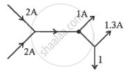
The figure below shows current in a part of electric circuit. The current I is ______.
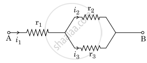
Three resistors having resistances r1, r2 and r3 are connected as shown in the given circuit. The ratio `i_3/i_1` of currents in terms of resistances used in the circuit is:
Three resistors having resistances r1, r2 and r3 are connected as shown in the given circuit. The ratio `"i"_3/"i"_1` of currents in terms of resistances used in the circuit is :
What is the advantage of using thick metallic strips to join wires in a potentiometer?
Why are alloys used for making standard resistance coils?
State the two Kirchhoff’s rules used in the analysis of electric circuits and explain them.
A 6-volt battery is connected to the terminals of a three-metre-long wire of uniform thickness and resistance of 100 ohms. The difference of potential between two points on the wire separated by a distance of 50 cm will be ______.
If currents \[I_1\] and \[I_2\] enter a junction and currents \[I_3\] and \[I_4\] leave it, which equation follows from Kirchhoff's First Law?
After a charge completes one full loop and returns to its starting point, what is the net change in potential?
Which sign convention is usually used for current entering a junction?
While moving in the direction of current through a resistor, how is the potential change treated?
What is the sign of the emf when moving from the negative terminal to the positive terminal of a cell?
