Advertisements
Advertisements
प्रश्न
Explain the determination of unknown resistance using meter bridge.
Advertisements
उत्तर
The meter bridge is another form of Wheatstone’s bridge. It consists of a uniform manganin wire AB of one meter length. This wire is stretched along a meter scale on a wooden board between two copper strips C and D. Between these two copper strips another copper strip E is mounted to enclose two gaps G1 and G2 An unknown resistance P is connected in G1 and a standard resistance Q is connected in G2.
A jockey (conducting wire) is connected to the terminal E on the central copper strip through a galvanometer (G) and a high resistance (HR). The exact position of jockey on the wire can be read on the scale. A Lechlanche cell and a key (K) are connected across the ends of the bridge wire.

Meter bridge
The position of the jockey on the wire is adjusted so that the galvanometer shows zero deflection. Let the point be J. The lengths AJ and JB of the bridge wire now replace the resistance R and S of the Wheatstone’s bridge. Then
`"P"/"Q" = "R"/"S" = ("R"' *"AJ")/("R"'*"JB")` ....(1)
where R’ is the resistance per unit length of wire
`"P"/"Q" = "AJ"/"JB" = l_1/l_2` ....(2)
P = Q `l_1/l_2` ....(3)
The bridge wire is soldered at the ends of the copper strips. Due to imperfect contact, some resistance might be introduced at the contact. These are called end resistances. This error can be eliminated, if another set of readings are taken with P and Q interchanged and the average value of P is found.
To find the specific resistance of the material of the wire in the coil P, the radius r and length l of the wire is measured. The specific resistance or resistivity r can be calculated using the relation.
Resistance = ρ - `l/"A"`
By rearranging the above equation, we get
ρ = Resistance `xx "A"/l`
If P is the unknown resistance, equation (4) becomes
ρ = P`(pi"r"^2)/l`
APPEARS IN
संबंधित प्रश्न
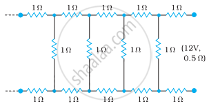
Determine the current drawn from a 12 V supply with internal resistance 0.5 Ω by the infinite network shown in the figure. Each resistor has 1 Ω resistance.
Given the resistances of 1 Ω, 2 Ω, 3 Ω, how will be combine them to get an equivalent resistance of (6/11) Ω?
State Kirchhoff's rules for an electric network. Using Kirchhoff's rules, obtain the balance condition in terms of the resistances of four arms of Wheatstone bridge.
In the circuit shown in the figure below, E1 and E2 are two cells having emfs 2 V and 3 V respectively, and negligible internal resistance. Applying Kirchhoff’s laws of electrical networks, find the values of currents l1 and I2.

The instrument for the accurate measurement of the e.m.f of a cell is ______.
Kirchhoff s second law is based on the law of conservation of ______
Kirchhoff’s junction rule is a reflection of ______.
- conservation of current density vector.
- conservation of charge.
- the fact that the momentum with which a charged particle approaches a junction is unchanged (as a vector) as the charged particle leaves the junction.
- the fact that there is no accumulation of charges at a junction.
The figure below shows two batteries, E1 and E2, having emfs of 18V and 10V and internal resistances of 1 Ω and 2 Ω, respectively. W1, W2 and W3 are uniform metallic wires AC, FD and BE having resistances of 8 Ω, 6 Ω and 10 Ω respectively. B and E are midpoints of the wires W1 and W2. Using Kirchhoff's laws of electrical circuits, calculate the current flowing in the wire W3:

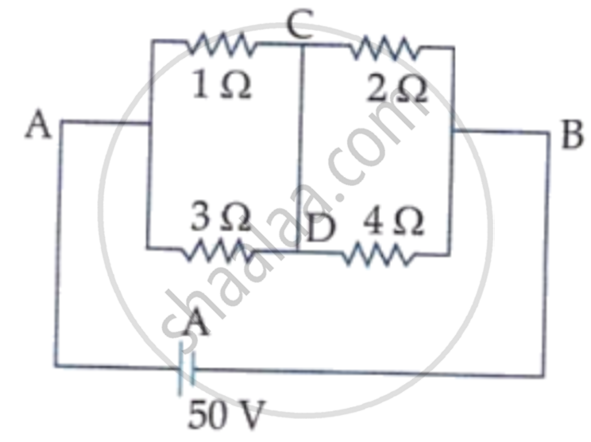
A constant voltage of 50 V is maintained between the points A and B of the circuit shown in the figure. The current through the branch CD of the circuit is: