Advertisements
Advertisements
प्रश्न
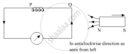
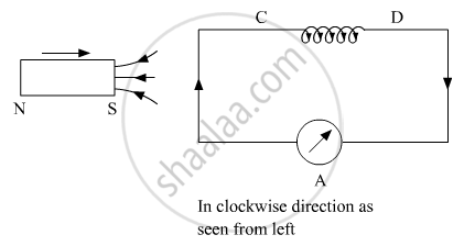
A bar magnet is moved in the direction indicated by the arrow between two coils PQ and CD. Predict the directions of induced current in each coil.

Advertisements
उत्तर
According to Lenz’s law the polarity of the induced emf is such that it opposes the change in magnetic flux responsible for its production.
Since North Pole of bar magnet is receding away from the coil so the right end of the coil will develop South Pole i.e. induced current as seen from the left end will be anticlockwise.
 Again, since South Pole is pushing towards the second coil so the left end of the coil will develop South Pole in order to repel it and decrease the flux i.e. induced current as seen from the left end will be clockwise.
संबंधित प्रश्न
Use Lenz’s law to determine the direction of induced current in the situation described by the figure:
A wire of irregular shape turning into a circular shape.

2 A 40 kg boy whose legs are 4 cm in area and 50 cm long falls through a height of 2 m without breaking his leg bones. If the bones can withstand stress of 0.9 x 10⁸ N/m2. The Young's modulus for the material of the bone is ______.
Energy dissipate in LCR circuit in
Lenz's law gives ______
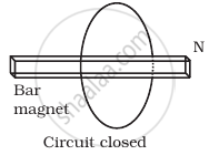
Consider a magnet surrounded by a wire with an on/off switch S (Figure). If the switch is thrown from the off position (open circuit) to the on position (closed circuit), will a current flow in the circuit? Explain.

A conducting wire XY of mass m and neglibile resistance slides smoothly on two parallel conducting wires as shown in figure. The closed circuit has a resistance R due to AC. AB and CD are perfect conductors. There is a ˆ. magnetic field `B = B(t)hatk`.
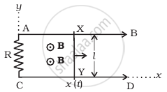
- Write down equation for the acceleration of the wire XY.
- If B is independent of time, obtain v(t) , assuming v(0) = u0.
- For (b), show that the decrease in kinetic energy of XY equals the heat lost in R.
Predict the direction of induced current in the situation described by the following figure.

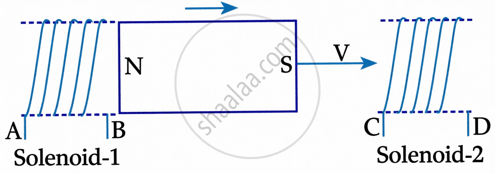
In the above diagram, a strong bar magnet is moving towards solenoid-2 from solenoid-1. The direction of induced current in solenoid-1 and that in solenoid-2, respectively, are through the directions:
What happens as the rate of change of magnetic flux becomes greater?
Why must continuous mechanical work be supplied to an AC generator?
