Advertisements
Advertisements
प्रश्न
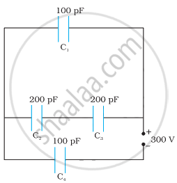
Obtain the equivalent capacitance of the network in Figure. For a 300 V supply, determine the charge and voltage across each capacitor.
Advertisements
उत्तर
Capacitance of capacitor C1 is 100 pF.
Capacitance of capacitor C2 is 200 pF.
Capacitance of capacitor C3 is 200 pF.
Capacitance of capacitor C4 is 100 pF.
Supply potential, V = 300 V
Capacitors C2 and C3 are connected in series.
Let their equivalent capacitance be C'
∴ `1/"C'" = 1/200 + 1/200 = 2/200`
∴ C' = 100 pF
Capacitors C1 and C' are in parallel. Let their equivalent capacitance be C''.
∴ `"C''" = "C'" + "C"_1`
= 100 + 100
= 200 pF
C'' and C4 are connected in series. Let their equivalent capacitance be C.
∴ `1/C = 1/("C''") + 1/("C"_4)`
= `1/200 + 1/100`
= `(2 + 1)/200`
C = `200/3` pF
Hence, the equivalent capacitance of the circuit is `200/3` pF.
Potential difference across C" = V"
Potential difference across C4 = V4
∴ `"V''" + "V"_4 = "V" = 300 "V"`
Charge on C4 is given by
Q4 = CV
= `200/3 xx 10^-12 xx 300`
= `2 xx 10^-8 "C"`
∴ `"V"_4 = "Q"_4/"C"_4`
= `(2 xx 10^-8)/(100 xx 10^-12)` = 200 V
∴ Voltage across C1 is given by
`"V"_1 = "V" - "V"_4`
= `300 - 200 = 100 "V"`
Hence, potential difference, V1, across C1 is 100 V.
Charge on C1 is given by,
`"Q"_1 = "C"_1"V"_1`
= `100 xx 10^-12 xx 100`
= `10^-8 "C"`
C2 and C3 have the same capacitances have a potential difference of 100 V together. Since C2 and C3 are in series, the potential difference across C2 and C3 is given by,
V2 = V3 = 50 V
Therefore, charge on C2 is given by,
`"Q"_2 = "C"_2"V"_2`
= `200 xx 10^-12 xx 50`
= `10^-8 "C"`
And charge on C3 is given by,
`"Q"_3 = "C"_3"V"_3`
= `200 xx 10^-12 xx 50`
= `10^-8 "C"`
Hence, the equivalent capacitance of the given circuit is `200/3` pF with
Q1 = 10−8 C, V1 = 100 V
Q2 = 10−8 C, V2 = 50 V
Q3 = 10−8 C, V3 = 50 V
Q4 = 2 × 10⁻⁸ C, V4 = 200 V
APPEARS IN
संबंधित प्रश्न
A capacitor of capacitance ‘C’ is charged to ‘V’ volts by a battery. After some time the battery is disconnected and the distance between the plates is doubled. Now a slab of dielectric constant, 1 < k < 2, is introduced to fill the space between the plates. How will the following be affected? (a) The electric field between the plates of the capacitor Justify your answer by writing the necessary expressions.
A capacitor of capacitance ‘C’ is charged to ‘V’ volts by a battery. After some time the battery is disconnected and the distance between the plates is doubled. Now a slab of dielectric constant, 1 < k < 2, is introduced to fill the space between the plates. How will the following be affected? (b) The energy stored in the capacitor Justify your answer by writing the necessary expressions
A spherical capacitor consists of two concentric spherical conductors, held in position by suitable insulating supports. Show that the capacitance of a spherical capacitor is given by
C = `(4piin_0"r"_1"r"_2)/("r"_1 - "r"_2)`
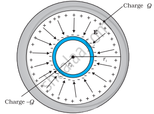
where r1 and r2 are the radii of outer and inner spheres, respectively.
A capacitor has capacitance C. Is this information sufficient to know what maximum charge the capacitor can contain? If yes, what is this charges? If no, what other information is needed?
Two conducting spheres of radii R1 and R2 are kept widely separated from each other. What are their individual capacitances? If the spheres are connected by a metal wire, what will be the capacitance of the combination? Think in terms of series−parallel connections.
A cylindrical capacitor is constructed using two coaxial cylinders of the same length 10 cm and of radii 2 mm and 4 mm. (a) Calculate the capacitance. (b) Another capacitor of the same length is constructed with cylinders of radii 4 mm and 8 mm. Calculate the capacitance.
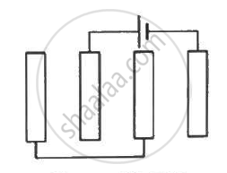
Each of the plates shown in figure has surface area `(96/∈_0) xx 10^-12` Fm on one side and the separation between the consecutive plates is 4⋅0 mm. The emf of the battery connected is 10 volts. Find the magnitude of the charge supplied by the battery to each of the plates connected to it.
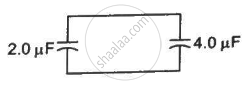
A capacitor of capacitance 2⋅0 µF is charged to a potential difference of 12 V. It is then connected to an uncharged capacitor of capacitance 4⋅0 µF as shown in figure . Find (a) the charge on each of the two capacitors after the connection, (b) the electrostatic energy stored in each of the two capacitors and (c) the heat produced during the charge transfer from one capacitor to the other.
The two square faces of a rectangular dielectric slab (dielectric constant 4⋅0) of dimensions 20 cm × 20 cm × 1⋅0 mm are metal-coated. Find the capacitance between the coated surfaces.
A parallel-plate capacitor of plate area A and plate separation d is charged to a potential difference V and then the battery is disconnected. A slab of dielectric constant K is then inserted between the plates of the capacitor so as to fill the space between the plates. Find the work done on the system in the process of inserting the slab.
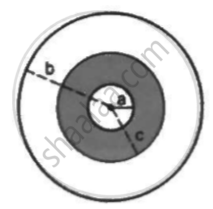
A sphercial capacitor is made of two conducting spherical shells of radii a and b. The space between the shells is filled with a dielectric of dielectric constant K up to a radius c as shown in figure . Calculate the capacitance.
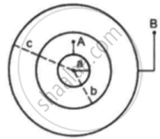
Suppose the space between the two inner shells is filled with a dielectric of dielectric constant K. Find the capacitance of the system between A and B.
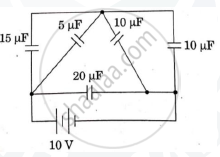
The figure show a network of five capacitors connected to a 10V battery. Calculate the charge acquired by the 5μF capacitor.
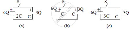
Three circuits, each consisting of a switch 'S' and two capacitors, are initially charged, as shown in the figure. After the switch has been closed, in which circuit will the charge on the left-hand capacitor
(i) increase,
(ii) decrease, and
(iii) remains the same? Give reasons.
Explain in detail the effect of a dielectric placed in a parallel plate capacitor.
The positive terminal of 12 V battery is connected to the ground. Then the negative terminal will be at ______.
The capacitance of a parallel plate capacitor is 60 µF. If the distance between the plates is tripled and area doubled then new capacitance will be ______.
A capacitor has charge 50 µC. When the gap between the plate is filled with glass wool, then 120 µC charge flows through the battery to capacitor. The dielectric constant of glass wool is ______.
If the plates of a parallel plate capacitor connected to a battery are moved close to each other, then:
- the charge stored in it. increases.
- the energy stored in it, decreases.
- its capacitance increases.
- the ratio of charge to its potential remains the same.
- the product of charge and voltage increases.
Choose the most appropriate answer from the options given below:
