Advertisements
Advertisements
प्रश्न
The variation of inductive reactance (XL) of an inductor with the frequency (f) of the ac source of 100 V and variable frequency is shown in fig.
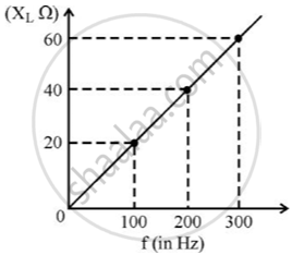
- Calculate the self-inductance of the inductor.
- When this inductor is used in series with a capacitor of unknown value and a resistor of 10 Ω at 300 s–1, maximum power dissipation occurs in the circuit. Calculate the capacitance of the capacitor.
Advertisements
उत्तर १
i. We know that XL = ωL and ω = 2π f
Where,
f = frequency in Hz
So, L = `X_L/(2 pi f)`
= `(20)/(2 pi(100))`
= `(40)/(2pi (200))`
= `(60)/(2pi(300))`
= 31.84 × 10⁻³
≈ 32 mH
ii. We know that power dissipation is maximum when,
XL = XC
⇒ ωL = `1/(omegaC)`
⇒ `C = 1/(omega^2L)`
⇒ C = `1/(4 pi^2 f^2 L)`
= `1/(4 xx 3.14 xx 3.14 xx 300 xx 300 xx 32 xx 10^-3)`
= 8.8 μF
उत्तर २
i. Given: From graph f = 100 Hz
XL = 20 Ω
Inductive reactance (XL) = 2π f L
So,
L = `X_L/(2 pi f)`
= `(20)/(2 pi xx 100)`
= 0.032 H
= 32 mH
ii. Given: f = 300 s−1
L = 0.032H
We know that power dissipation is maximum when,
2π f L = `1/(2 pi f C)`
2π × 300 × 0.032 = `1/(2 pi xx 300 xx C)`
∴ C = 8.8 × 10⁻⁶ F
= 8.8 μF
संबंधित प्रश्न
Two capacitors each having capacitance C and breakdown voltage V are joined in series. The capacitance and the breakdown voltage of the combination will be
Suppose, one wishes to construct a 1⋅0 farad capacitor using circular discs. If the separation between the discs be kept at 1⋅0 mm, what would be the radius of the discs?
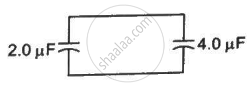
A capacitor of capacitance 2⋅0 µF is charged to a potential difference of 12 V. It is then connected to an uncharged capacitor of capacitance 4⋅0 µF as shown in figure . Find (a) the charge on each of the two capacitors after the connection, (b) the electrostatic energy stored in each of the two capacitors and (c) the heat produced during the charge transfer from one capacitor to the other.
The two square faces of a rectangular dielectric slab (dielectric constant 4⋅0) of dimensions 20 cm × 20 cm × 1⋅0 mm are metal-coated. Find the capacitance between the coated surfaces.
A parallel-plate capacitor of capacitance 5 µF is connected to a battery of emf 6 V. The separation between the plates is 2 mm. (a) Find the charge on the positive plate. (b) Find the electric field between the plates. (c) A dielectric slab of thickness 1 mm and dielectric constant 5 is inserted into the gap to occupy the lower half of it. Find the capacitance of the new combination. (d) How much charge has flown through the battery after the slab is inserted?
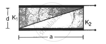
A capacitor is formed by two square metal-plates of edge a, separated by a distance d. Dielectrics of dielectric constant K1 and K2 are filled in the gap as shown in figure . Find the capacitance.
Three capacitors C1 = 3μF, C2 = 6μF, and C3 = 10μF are connected to a 50 V battery as shown in Figure below:

Calculate:
(i) The equivalent capacitance of the circuit between points A and B.
(ii) The charge on C1.
- Charge on each capacitor remains same and equals to the main charge supplied by the battery.
- Potential difference and energy distribute in the reverse ratio of capacitance.
- Effective capacitance is even les than the least of teh individual capacitances.
A 5µF capacitor is charged fully by a 220 V supply. It is then disconnected from the supply and is connected in series to another uncharged 2.5 µF capacitor If the energy change during the charge redistribution is `"X"/100`J then value of X to the 100 nearest integer is ______.
In a series combination, which capacitor gets a larger potential difference?
