Advertisements
Advertisements
प्रश्न
A capacitor of capacitance C is charged fully by connecting it to a battery of emf E. It is then disconnected from the battery. If the separation between the plates of the capacitor is now doubled, how will the following change?
(i) charge stored by the capacitor.
(ii) Field strength between the plates.
(iii) Energy stored by the capacitor.
Justify your answer in each case.
Advertisements
उत्तर
(i)The charge stored on the capacitor does not change because of the law of conservation of charges.
(ii) The field strength between the plates is
`E=sigma/epsilon_0=Q/(Aepsilon_0)`
Hence, we see that the field strength is independent of the distance between the plates. So, the field strength also remains the same.
(iii)The energy stored in the capacitor is
`W=Q^2/(2C)`
Now, when the distance between the plates is doubled, the capacitance becomes half. Hence, the energy stored will also double.
APPEARS IN
संबंधित प्रश्न
A capacitor of unknown capacitance is connected across a battery of V volts. The charge stored in it is 300 μC. When potential across the capacitor is reduced by 100 V, the charge stored in it becomes 100 μC. Calculate The potential V and the unknown capacitance. What will be the charge stored in the capacitor if the voltage applied had increased by 100 V?
The plates of a parallel-plate capacitor are made of circular discs of radii 5⋅0 cm each. If the separation between the plates is 1⋅0 mm, what is the capacitance?
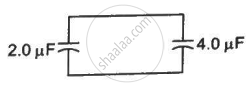
A capacitor of capacitance 2⋅0 µF is charged to a potential difference of 12 V. It is then connected to an uncharged capacitor of capacitance 4⋅0 µF as shown in figure . Find (a) the charge on each of the two capacitors after the connection, (b) the electrostatic energy stored in each of the two capacitors and (c) the heat produced during the charge transfer from one capacitor to the other.
A parallel-plate capacitor with the plate area 100 cm2 and the separation between the plates 1⋅0 cm is connected across a battery of emf 24 volts. Find the force of attraction between the plates.
Three capacitors C1 = 3μF, C2 = 6μF, and C3 = 10μF are connected to a 50 V battery as shown in Figure below:

Calculate:
(i) The equivalent capacitance of the circuit between points A and B.
(ii) The charge on C1.
Derive the expression for resultant capacitance, when the capacitor is connected in series.
Two similar conducting spheres having charge+ q and -q are placed at 'd' seperation from each other in air. The radius of each ball is r and the separation between their centre is d (d >> r). Calculate the capacitance of the two ball system ______.

A leaky parallel plate capacitor is filled completely with a material having dielectric constant K = 5 and electric conductivity σ = 7.4 × 10⁻¹² Ω-1 m-1. If the charge on the plate at the instant t = 0 is q = 8.85 µC, then the leakage current at the instant t = 12 s is ______ × 10-1 µA.
The plates of a parallel plate capacitor are separated by d. Two slabs of different dielectric constant K1 and K2 with thickness `3/8 d and d/2`, respectively, are inserted in the capacitor. Due to this, the capacitance becomes two times larger than when there is nothing between the plates. If K1 = 1.25 K, the value of K1 is:
