Advertisements
Advertisements
प्रश्न
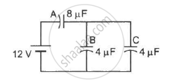
Find the charge appearing on each of the three capacitors shown in figure .
Advertisements
उत्तर
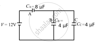
Let us first find the equivalent capacitance. It can be observed from the circuit diagram that capacitors B and C are in parallel and are in series with capacitor A.
The equivalent capacitance can be calculated as follow :-
`1/C_(eq) = 1/C_A + 1/(C_B+C_C`
`1/C_(eq) = 1/8 + 1/(4+4) = 1/8+1/8`
`⇒ 1/C_(eq) = 2/8`
`⇒ C_(eq) = 4 "uF"`
Capacitors B and C are parallel and are in series with capacitor A. The equivalent capacitance of capacitors B and C is given by
(4 + 4) μF = 8 μF
It is the same as the capacitance of capacitor A. Therefore, equal potential difference will be there on capacitor A and the system of capacitors B and C.
Now,
Potential difference across capacitor A = 6 V
Thus,
Charge on capacitor A = (8 µF) × (6 V) = 48 µC
And,
Potential difference across capacitors B and C = 6 V
Charge on capacitor B = (4 µF) × (6 V) = 24 µF
Charge on capacitor C = (4 µF) × (6 V) = 24 µF
APPEARS IN
संबंधित प्रश्न
A capacitor of capacitance ‘C’ is charged to ‘V’ volts by a battery. After some time the battery is disconnected and the distance between the plates is doubled. Now a slab of dielectric constant, 1 < k < 2, is introduced to fill the space between the plates. How will the following be affected? (a) The electric field between the plates of the capacitor Justify your answer by writing the necessary expressions.
A capacitor of unknown capacitance is connected across a battery of V volts. The charge stored in it is 360 μC. When potential across the capacitor is reduced by 120 V, the charge stored in it becomes 120 μC.
Calculate:
(i) The potential V and the unknown capacitance C.
(ii) What will be the charge stored in the capacitor, if the voltage applied had increased by 120 V?
The capacitance of a capacitor does not depend on
The plates of a parallel-plate capacitor are made of circular discs of radii 5⋅0 cm each. If the separation between the plates is 1⋅0 mm, what is the capacitance?
Suppose, one wishes to construct a 1⋅0 farad capacitor using circular discs. If the separation between the discs be kept at 1⋅0 mm, what would be the radius of the discs?
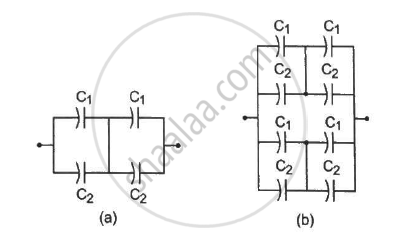
Take `C_1 = 4.0 "uF" and C_2 = 6.0 "uF"` in figure . Calculate the equivalent capacitance of the combination between the points indicated.
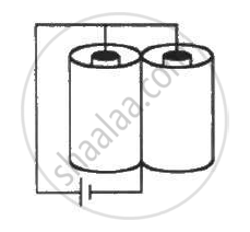
The outer cylinders of two cylindrical capacitors of capacitance 2⋅2 µF each, are kept in contact and the inner cylinders are connected through a wire. A battery of emf 10 V is connected as shown in figure . Find the total charge supplied by the battery to the inner cylinders.
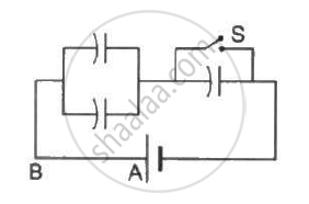
Each capacitor shown in figure has a capacitance of 5⋅0 µF. The emf of the battery is 50 V. How much charge will flow through AB if the switch S is closed?
A 5⋅0 µF capacitor is charged to 12 V. The positive plate of this capacitor is now connected to the negative terminal of a 12 V battery and vice versa. Calculate the heat developed in the connecting wires.
A parallel-plate capacitor has plate area 100 cm2 and plate separation 1⋅0 cm. A glass plate (dielectric constant 6⋅0) of thickness 6⋅0 mm and an ebonite plate (dielectric constant 4⋅0) are inserted one over the other to fill the space between the plates of the capacitor. Find the new capacitance.
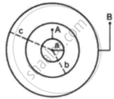
Suppose the space between the two inner shells is filled with a dielectric of dielectric constant K. Find the capacitance of the system between A and B.
You are provided with 8 μF capacitors. Show with the help of a diagram how you will arrange minimum number of them to get a resultant capacitance of 20 μF.
- Charge on each capacitor remains same and equals to the main charge supplied by the battery.
- Potential difference and energy distribute in the reverse ratio of capacitance.
- Effective capacitance is even les than the least of teh individual capacitances.
The work done in placing a charge of 8 × 10–18 coulomb on a condenser of capacity 100 micro-farad is ______.
Three capacitors 2µF, 3µF, and 6µF are joined in series with each other. The equivalent capacitance is ____________.
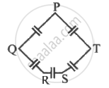
Five capacitor each of capacitance value C are connected as shown in the figure. The ratio of capacitance between P to R, and the capacitance between P and Q is ______.
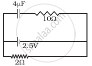
A capacitor of 4 µ F is connected as shown in the circuit (Figure). The internal resistance of the battery is 0.5 Ω. The amount of charge on the capacitor plates will be ______.
For a given capacitor, what fixes its capacitance?
In a parallel combination, which quantity is the same across each capacitor?
Which statement describes the voltage and use of a parallel combination?
