Advertisements
Advertisements
प्रश्न
An electronics hobbyist is building a radio which requires 150 Ω in her circuit, but she has only 220 Ω, 79 Ω, and 92 Ω resistors available. How can she connect the available resistors to get the desired value of resistance?
Advertisements
उत्तर
Available resistances = 220 Ω, 79 Ω 92 Ω
Case I:
If 3 resistors are connected in series, then
RS = R1 + R2 + R3 = 220 + 79 + 92 = 391
This value is greater than the required resistance so it is not possible.
Case II:
If 3 resistors are connected in parallel, then
`1/"R"_"p" = 1/"R"_1 + 1/"R"_2 + 1/"R"_3`
`1/"R"_"p" = 1/220 + 1/79 + 1/92` = 0.0279
Rp = 35.84 This does not meet the requirement.
Case III:
If R1 and R2 are connected in parallel and R3 in series
`1/"R"_"p" = 1/"R"_1 + 1/"R"_2 = 1/220 + 1/79 = 0.0172`
`=> "R"_"p" = 58.14 Omega`
This meets the requirement.
APPEARS IN
संबंधित प्रश्न
What will be the change in the current if the potential difference is kept constant and the resistance of the circuit is made four times?
- It will remain unchanged.
- It will become four times.
- It will become one-fourth.
- It will become half.
What is an Ohmic resistor?
Write the formula of resistivity
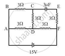
In the circuit shown in the figure, find the total resistance of the circuit and the current in the arm AD.
State and define Ohm’s law.
Choose the correct alternative.
Which of the following is an ohmic conductor?
What is non ohmic device?
Write a short note on superconductors?
A current of 2amp flowing through a conductor produced 80 joule of heat in 10 sec. The resistance of the conductor is:-
The circuit depicted in the figure is employed for studying Ohm’s Law. Instead of using a standard resistor, a student opts for a glass tube filled with mercury (tube 1), connected to the circuit through two electrodes, E1 and E2. He records the readings of the ammeter and voltmeter, thereby calculating the resistance. The student repeats the experiment by substituting tube 1 with tube 2, where the same amount of mercury fills tube 2.
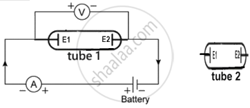
Neglecting internal resistance of the cell use (> or < or =) to compare:
- the resistance in both the cases.
- the voltmeter readings in both the cases.
- the specific resistance in both the cases.
