Topics
Circular Motion
- Angular Displacement
- Angular Velocity
- Angular Acceleration
- Angular Velocity and Its Relation with Linear Velocity
- Uniform Circular Motion (UCM)
- Radial Acceleration
- Dynamics of Uniform Circular Motion - Centripetal Force
- Centrifugal Forces
- Banking of Roads
- Vertical Circular Motion Due to Earth’s Gravitation
- Equation for Velocity and Energy at Different Positions of Vertical Circular Motion
- Kinematical Equations for Circular Motion in Analogy with Linear Motion.
Rotational Dynamics
- Rotational Dynamics
- Circular Motion and Its Characteristics
- Applications of Uniform Circular Motion
- Vertical Circular Motion
- Moment of Inertia as an Analogous Quantity for Mass
- Radius of Gyration
- Theorems of Perpendicular and Parallel Axes
- Angular Momentum or Moment of Linear Momentum
- Expression for Torque in Terms of Moment of Inertia
- Conservation of Angular Momentum
- Rolling Motion
- Overview: Rotational Dynamics
Gravitation
- Newton’s Law of Gravitation
- Periodic Time
- Kepler’s Laws
- Binding Energy and Escape Velocity of a Satellite
- Weightlessness
- Variation of ‘G’ Due to Lattitude and Motion
- Variation in the Acceleration>Variation in Gravity with Altitude
- Communication satellite and its uses
- Composition of Two S.H.M.’S Having Same Period and Along Same Line
Mechanical Properties of Fluids
- Fluid and Its Properties
- Thrust and Pressure
- Pressure of liquid
- Pressure Exerted by a Liquid Column
- Atmospheric Pressure
- Gauge Pressure and Absolute Pressure
- Hydrostatic Paradox
- Pascal’s Law
- Application of Pascal’s Law
- Measurement of Atmospheric Pressure
- Mercury Barometer (Simple Barometer)
- Open Tube Manometer
- Surface Tension
- Molecular Theory of Surface Tension
- Surface Tension and Surface Energy
- Angle of Contact
- Effect of Impurity and Temperature on Surface Tension
- Excess Pressure Across the Free Surface of a Liquid
- Explanation of Formation of Drops and Bubbles
- Capillarity and Capillary Action
- Fluids in Motion
- Critical Velocity and Reynolds Number
- Viscous Force or Viscosity
- Stokes’ Law
- Terminal Velocity
- Continuous and Discontinuous Functions
- Bernoulli's Equation
- Applications of Bernoulli’s Equation
- Overview: Mechanical Properties of Fluids
Kinetic Theory of Gases and Radiation
- Gases and Its Characteristics
- Classification of Gases: Real Gases and Ideal Gases
- Mean Free Path
- Expression for Pressure Exerted by a Gas
- Root Mean Square (RMS) Speed
- Interpretation of Temperature in Kinetic Theory
- Law of Equipartition of Energy
- Specific Heat Capacity
- Absorption, Reflection, and Transmission of Heat Radiation
- Perfect Blackbody
- Emission of Heat Radiation
- Kirchhoff’s Law of Heat Radiation and Its Theoretical Proof
- Spectral Distribution of Blackbody Radiation
- Wien's Displacement Law
- Stefan-boltzmann Law of Radiation
- Overview: Kinetic Theory of Gases and Radiation
Angular Momentum
- Definition of M.I., K.E. of Rotating Body
- Rolling Motion
- Physical Significance of M.I (Moment of Inertia)
- Torque and Angular Momentum
- Theorems of Perpendicular and Parallel Axes
- M.I. of Some Regular Shaped Bodies About Specific Axes
Thermodynamics
- Thermodynamics
- Thermal Equilibrium
- Measurement of Temperature
- Heat, Internal Energy and Work
- First Law of Thermodynamics
- Thermodynamic State Variables and Equation of State
- Thermodynamic Process
- Heat Engine
- Refrigerators and Heat Pumps
- Entropy and Second Law of Thermodynamics
- Carnot Cycle and Carnot Engine
- Overview: Thermodynamics
Oscillations
- Periodic and Oscillatory Motion
- Simple Harmonic Motion (S.H.M.)
- Differential Equation of Linear S.H.M.
- Projection of U.C.M.(Uniform Circular Motion) on Any Diameter
- Phase of K.E (Kinetic Energy)
- K.E.(Kinetic Energy) and P.E.(Potential Energy) in S.H.M.
- Composition of Two S.H.M.’S Having Same Period and Along Same Line
- Some Systems Executing Simple Harmonic Motion
Oscillations
- Oscillations
- Explanation of Periodic Motion
- Linear Simple Harmonic Motion (S.H.M.)
- Differential Equation of Linear S.H.M.
- Acceleration (a), Velocity (v) and Displacement (x) of S.H.M.
- Amplitude (A), Period (T) and Frequency (N) of S.H.M.
- Reference Circle Method
- Phase in S.H.M.
- Graphical Representation of S.H.M.
- Composition of Two S.H.M.’S Having Same Period and Along Same Line
- The Energy of a Particle Performing S.H.M.
- Simple Pendulum
- Angular S.H.M. and It's Differential Equation
- Damped Oscillations
- Free Oscillations, Forced Oscillations and Resonance Oscillations
- Periodic and Oscillatory Motion
- Overview: Oscillations
Elasticity
- Eneral Explanation of Elastic Property
- Stress and Strain
- Hooke’s Law
- Elastic Energy
- Elastic Constants and Their Relation
- Determination of ‘Y’
- Behaviour of Metal Wire Under Increasing Load
- Application of Elastic Behaviour of Materials
Surface Tension
- Molecular Theory of Surface Tension
- Surface Tension
- Capillarity and Capillary Action
- Effect of Impurity and Temperature on Surface Tension
Superposition of Waves
Wave Optics
- Concept of Wave Optics
- Nature of Light
- Light as a Wave
- Huygens Principle
- Reflection of Light at a Plane Surface
- Refraction of Light at a Plane Boundary Between Two Media
- Polarisation of Light
- Interference
- Diffraction of Light
- Resolving Power
- Overview: Wave Optics
Wave Motion
- Wave Motion Introduction
- Simple Harmonic Progressive Waves,
- Reflection of Transverse and Longitudinal Waves
- Change of Phase
- Principle of Superposition of Waves
- Formation of Beats
- Beats
Stationary Waves
- Study of Vibrations in a Finite Medium
- Formation of Stationary Waves on String
- Study of Vibrations of Air Columns
- Free and Forced Vibrations
- Forced Oscillations and Resonance
Electrostatics
- Concept of Electrostatics
- Application of Gauss' Law
- Electric Potential and Potential Difference
- Electric Potential Due to a Point Charge
- Equipotential Surfaces
- Electrical Energy of Two Point Charges and of a Dipole in an Electrostatic Field
- Free and Bound Charges
- Combination of Capacitors
- Displacement Current
- Energy Stored in a Charged Capacitor
- Van De Graaff Generator
- Uniformly Charged Infinite Plane Sheet and Uniformly Charged Thin Spherical Shell (Field Inside and Outside)
- Overview: Electrostatics
Current Electricity
Kinetic Theory of Gases and Radiation
- Concept of an Ideal Gas
- Assumptions of Kinetic Theory of Gases
- Derivation for Pressure of a Gas
- Degrees of Freedom
- Derivation of Boyle’s Law
- Thermal Equilibrium
- First Law of Thermodynamics
- Heat Engine
- Temperature and Heat
- Qualitative Ideas of Black Body Radiation
- Wien's Displacement Law
- Green House Effect
- Stefan's Law
- Maxwell Distribution
- Specific Heat Capacities - Gases
- Law of Equipartition of Energy
Wave Theory of Light
Magnetic Fields Due to Electric Current
- Magnetic Fields Due to Electric Current
- Magnetic force
- Cyclotron
- Helical Motion
- Magnetic Force on a Wire Carrying a Current
- Force on a Closed Circuit in a Magnetic Field
- Torque on a Current-Loop in a Uniform Magnetic Field
- Magnetic Dipole Moment
- Magnetic Potential Energy of a Dipole
- Magnetic Field Due to a Current-carrying Conductor: Biot-savart's Law
- Force of Attraction Between Two Long Parallel Wires
- Magnetic Field Produced by a Current in a Circular Arc of a Wire
- Applications of Biot-Savart's Law > Magnetic Field at the Axis of a Circular Current-carrying Loop
- Magnetic Lines for a Current Loop
- Ampere’s Circuital Law
- Applications of Ampere’s Circuital Law > Magnetic Field of a Toroidal Solenoid
- Overview: Magnetic Fields Due to Electric Current
Magnetic Materials
- Magnetic Materials
- Torque Acting on a Magnetic Dipole in a Uniform Magnetic Field
- Origin of Magnetism in Materials
- Magnetisation and Magnetic Intensity
- Magnetic Properties of Materials
- Classification of Magnetic Materials
- Hysteresis: Retentivity and Coercivity
- Permanent Magnet
- Magnetic Shielding
- Overview: Magnetic Materials
Interference and Diffraction
- Interference of Light
- Conditions for Producing Steady Interference Pattern
- Interference of Light Waves and Young’s Experiment
- Analytical Treatment of Interference Bands
- Measurement of Wavelength by Biprism Experiment
- Fraunhofer Diffraction Due to a Single Slit
- Rayleigh’s Criterion
- Resolving Power of a Microscope and Telescope
- Difference Between Interference and Diffraction
Electromagnetic Induction
- Electromagnetic Induction
- Faraday's Laws of Electromagnetic Induction
- Lenz's Law
- Flux of a Vector Field
- Motional Electromotive Force (e.m.f.)
- Induced Emf in a Stationary Coil in a Changing Magnetic Field
- Generators
- Back Emf and Back Torque
- Induction and Energy Transfer
- Eddy Currents or Foucault Currents
- Self Inductance
- Energy Stored in a Magnetic Field
- Energy Density of a Magnetic Field
- Mutual Inductance
- Transformers
- Overview of Electromagnetic Induction
Electrostatics
- Mechanical Force on Unit Area of a Charged Conductor
- Energy Density of a Medium
- Concept of Condenser
- The Parallel Plate Capacitor
- Capacity of Parallel Plate Condenser
- Effect of Dielectric on Capacitance
- Energy of Charged Condenser
- Condensers in Series and Parallel,
- Van-deGraaff Generator
AC Circuits
- AC Circuits
- Values of Alternating Current
- Phasors
- AC Voltage Applied to a Resistor
- AC Voltage Applied to an Inductor
- AC Voltage Applied to a Capacitor
- AC Voltage Applied to a Series LCR Circuit
- Power in AC Circuit
- LC Oscillations
- Electric Resonance
- Sharpness of Resonance: Q Factor
- Choke Coil
- Overview: AC Circuits
Current Electricity
- Meter Bridge
Dual Nature of Radiation and Matter
Magnetic Effects of Electric Current
Magnetism
Structure of Atoms and Nuclei
- Structure of the Atom and Nucleus
- Thomson’s Atomic Model
- Geiger-marsden Experiment
- Lord Rutherford’s Atomic model
- Atomic Spectra
- Neils Bohr’s Model of an Atom
- Atomic Nucleus
- Constituents of a Nucleus
- Isotopes
- Atomic and Nuclear Masses
- Size of the Nucleus
- Mass Defect and Binding Energy
- Binding Energy Curve
- Forms of Energy > Nuclear Energy
- Nuclear Binding Energy
- Radioactive Decays
- Law of Radioactive Decay
- Overview: Structure of Atoms and Nuclei
Semiconductor Devices
Electromagnetic Inductions
- Electromagnetic Induction
- Self Inductance
- Mutual Inductance
- Transformers
- Need for Displacement Current
- Coil Rotating in Uniform Magnetic Induction
- A.C. Generator
- Reactance and Impedance
- LC Oscillations
- Inductance and Capacitance
- Resonant Circuits
- Power in AC Circuit
- Lenz’s Law and Conservation of Energy
Electrons and Photons
Atoms, Molecules and Nuclei
- Alpha-particle Scattering and Rutherford’s Nuclear Model of Atom
- Bohr’s Model for Hydrogen Atom
- Hydrogen Spectrum
- Atomic Masses and Composition of Nucleus
- Radioactivity
- Law of Radioactive Decay
- Atomic Mass, Mass - Energy Relation and Mass Defect
- Nuclear Binding Energy
- Nuclear Fusion
- de-Broglie Relation
- Wave Nature of Matter
- Wavelength of an Electron
- Davisson and Germer Experiment
- Continuous and Characteristics X-rays
- Mass Defect and Binding Energy
Semiconductors
- Energy Bands in Solids
- Extrinsic Semiconductor
- Applications of n-type and p-type Semiconductors
- Special Purpose P-n Junction Diodes
- Semiconductor Diode
- Voltage Regulator
- I-V Characteristics of Led
- Transistor and Characteristics of a Transistor
- Transistor as an Amplifier (Ce-configuration)
- Transistor as a Switch
- Oscillators
- Digital Electronics and Logic Gates
Communication Systems
CISCE: Class 10
Definition: A.C. Generator
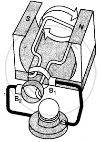
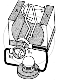
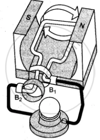
An a.c. generator is a device which converts the mechanical energy into the electrical energy using the principle of electromagnetic induction.
Principle
Whenever the magnetic flux linked with a closed coil changes with time, an electromotive force (EMF) is induced in it. This is Faraday's Law of Electromagnetic Induction.
Faraday's Law (Mathematical Form):
ε = −N × (dΦB / dt)
- The negative sign indicates Lenz's Law — the induced EMF opposes the change in flux.
- In an A.C. generator, rotation of the coil in a uniform magnetic field causes a continuous change in flux, thereby inducing a continuously alternating EMF.
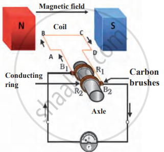
Components & Construction
Labels required:
- Armature Coil (N turns, Area A)
- Magnetic Field B (arrows from N to S)
- Slip Rings (R₁ and R₂)
- Carbon Brushes (B₁ and B₂)
- External Load/Resistance
- Rotor Shaft
Components Table
| Component | Material | Function | |
|---|---|---|---|
| 1 | Armature Coil | Insulated copper wire on an iron core | Rotates in field B; site of EMF induction |
| 2 | Field Magnet | Permanent magnet or electromagnet | Provides a uniform magnetic field B |
| 3 | Slip Rings | Copper/brass (2 rings) | Maintain continuous contact between the rotating coil and the brushes |
| 4 | Carbon Brushes | Carbon (2 brushes: B₁, B₂) | Press against slip rings; carry current to the external circuit |
| 5 | Rotor Shaft | Steel | Holds an armature; connected to a mechanical energy source |
| 6 | External Load | Resistance R | Receives and utilises the alternating current |
Working
- Mechanical energy is supplied to the rotor shaft (steam, water from a dam, wind, etc.)
- The armature coil rotates in a uniform magnetic field B with constant angular speed ω
- The angle θ between area vector A of the coil and B changes: θ = ωt
- This causes the magnetic flux through the coil to change continuously
- By Faraday's Law, changing flux induces an alternating EMF
- Current reverses direction every half rotation
- Slip rings allow continuous rotation while maintaining electrical contact
- Alternating current (AC) flows in the external load
Mathematical Derivation of EMF
Step 1: Magnetic Flux at Time t
At t = 0, the coil is perpendicular to B (flux is maximum). At time t:
- θ = ωt
- ΦB = BA cos(ωt) [for one turn]
Total flux linkage (N turns): NΦB = NBA cos(ωt) ...(1)
Step 2: Apply Faraday's Law
- ε = −d(NΦB)/dt
= −d/dt [NBA cos(ωt)]
= −NBA × [−ω sin(ωt)]
∴ ε = NBAω sin(ωt) ...(2)
Step 3: Peak EMF
EMF is maximum when sin(ωt) = ±1 → θ = 90° or 270°
- ε₀ = NBAω ...(3)
Therefore:
- ε = ε₀ sin(ωt) ...(4) ← STANDARD FORM
Step 4: In Terms of Frequency
Since ω = 2πn:
- ε = NBA(2πn) sin(2πnt) ...(5)
Step 5: Instantaneous Current
- I = ε/R = (ε₀/R) sin(ωt) = I₀ sin(ωt) ...(6)
where I₀ = ε₀/R (peak current)
Example
Kamla pedals a stationary bicycle (like a gym cycle). The pedals are connected to a 100-turn coil that rotates inside a magnetic field. The question asks: What is the maximum voltage (peak EMF) the coil generates?
Given Values
| Quantity | Symbol | Value |
|---|---|---|
| Number of turns | N | 100 |
| Area of coil | A | 0.10 m² |
| Frequency of rotation | n | 0.5 rev/s (half a revolution per second) |
| Magnetic field | B | 0.01 T |
What Is Being Found?
The maximum (peak) EMF is the highest voltage the rotating coil can generate.
Formula Used
Key Takeaway
This example illustrates that even a simple human-powered bicycle can act as an AC generator — just on a very small scale. The low output (0.314 V) is because:
- The coil rotates very slowly (only 0.5 Hz)
- The magnetic field is weak (0.01 T)
In real power stations, N, B, A, and ω are all much larger, which is why generators there produce voltages in the kilovolt range (e.g., 11 kV to 33 kV).
Real-Life Applications
| Application | Energy Source | How a Generator Is Used |
|---|---|---|
| Thermal Power Plant | Coal → Steam | Steam rotates the turbine connected to the armature |
| Hydroelectric Plant | Falling water | Water rotates turbine blades |
| Nuclear Power Plant | Nuclear fuel (U-235) | Heat → Steam → Turbine → Generator |