Advertisements
Advertisements
Question
From the diagram given below. answer the question that follows:
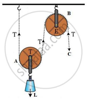
1) What kind of pulleys are A and B?
2) State the purpose of pulley B.
3) What effort has to be applied at C just raise the load L = 20 kgf?
(Neglect the weight of pulley A and friction)
Advertisements
Solution
1) The pulley A is a single movable pulley and B is a single fixed pulley.
2) Pulley B is a single fixed type pulley. Its purpose is to change the direction of the effort applied.
3) The effort at C is equal to the load. This is because B is a single fixed pulley and its mechanical advantage is 1. So, we have
M.A. = L/E = 1
∴ E = L = 20 kgf
APPEARS IN
RELATED QUESTIONS
State two functions of a machine.
What is the justification for using the pulley then ?
Explain how a gear system can be used to obtain Change in direction of rotation. Given one example.
Define the following term in reference to a gear system for Gear ratio ?
What should be the gear ration of a car : equal to 1, less than 1 or greater than 1, while gaining speed on the road ?
In a gear system, the gear ration of the driving wheel A and driven wheel B is 10:1. To rotate the driven wheel B in the direction of driving wheel A, the driving wheel A is engaged with other wheel C. what should be the gear ratio of the wheels A and C?
What is the use of a fixed pulley?
In the alongside the figure of two pulleys shown a system in which one pulley is fixed and the other is movable. What is the velocity ratio of the system?
An effort of 600 N is needed to lift a weight of 1000 N. What are the mechanical advantage and efficiency of the pulley system?
A ‘block and tackle’ system used 3 pulleys in the lower block and 4 pulleys in the upper block. What is the ‘velocity ratio’ of this system? If the load is to be lifted by a person capable of applying a maximum effort of 1000 N, what is the maximum load than can be lifted under ideal conditions?
The actual maximum load that gets lifted turns out to be 6300 N. What are the values of the actual M.A. and efficiency of the set-up?
A block and tackle system of pulleys has a velocity ratio of 4.
- Draw a labelled diagram of the system indicating clearly the direction of the load and effort.
- Calculate the potential energy of the load 100 kgf lifted by this pulley to a height 5 m. (g = 10 ms−2)
