Advertisements
Advertisements
Question
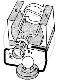
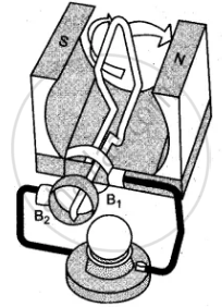
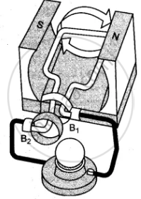
The given figures 1 to 3 show the working of a simple A.C. generator. Study the diagrams and answers of the following questions.
(i) State and explain the principle underlying the working of a simple generator.
(ii) Where is the loop of wire placed?
(iii) What happens when the loop is rotated?
(iv) Indicate the direction of the current flow through the wire for the first half of the turn (in first figure). Name and state the rule used in finding the direction of the current.
(v) Indicate the direction of the current for the case shown in second figure.
(vi) Indicate the direction of current in the outer circuit (i.e., electric bulb) in first and third figure.
(vii) What type of current is shown in the above diagrams? Explain.
Advertisements
Solution
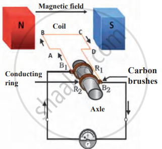
(i) The generator works on the principle of Electromagnetic Induction. Whenever the flux passing through a closed circuit changes, e.m.f. is induced in it and a current begins to flow. Its direction is given by Fleming’s Right Hand Rule or Lenz Law. As long as the loop is moving within the magnetic field an electric current will flow.
(ii) The loop of wire is placed between the two poles of a ‘U’-shaped magnet.
(iii) When the loop of wire is rotated between the two poles of a ‘U’-shaped magnet an electric current flows through the wire.
(iv) As rotation of the coil is the clockwise direction and the direction of magnetic field is from right to left, the current will flow in the anticlockwise direction, i.e., from B2 and B1. The law used is Lenz’s law.
Lenz’s law: “The direction of the induced e.m.f. is such that it opposes the change responsible for its production.”
(v) No electric current flows when the loop of wire is halfway through the turn, i.e., at an angle of 90° [as sin 90° = 0.]
(vi) First figure: From brush B2 to B1
Third figure: From brush B1 to B2
(vii) The type of current shown is an alternating current or A.C. current. When the loop of wire makes the second half of the turn (fig., the direction of the electric current through the bulb is reversed and it flows back in the opposite direction.
RELATED QUESTIONS
A coil of insulated copper wire is connected to a galvanometer. What will happen if a bar magnet is pushed into the coil?
Why are Thermal Power Stations usually located near a river?
Explain the principle of an electric generator.
An electric generator converts:
(a) electrical energy into mechanical energy.
(b) mechanical energy into heat energy.
(c) electrical energy into chemical energy.
(d) mechanical energy into electrical energy.
Draw a labelled diagram of a simple a.c. generator.
State one advantage of using a.c. over d.c.
Observe the figure and write the answers to the questions asked.
- The construction shown in the figure is of which device?
- Explain the principle on which this device works.
- Write any three uses of this device.
Draw a neat diagram of an AC generator and explain its working.
To convert an AC generator into DC generator ____________.
A coil of insulated copper wire is connected to a galvanometer. What will happen if a bar magnet is withdrawn from inside the coil?
