Advertisements
Advertisements
Question
Fig. shows a simple form of an A.C. generator.
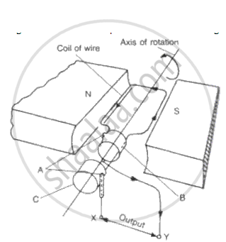
(a) Name the parts labeled A and B.
(b) What would be the effect of doubling the number of turns on the coil if the speed of rotation remains unchanged?
(c) Which of the output terminals is positive if the coil is rotating in the
direction shown in the diagram (anticlockwise)?
( d ) What is the position of the rotating coil when p.d. across its ends is zero? Explain why p.d. is zero when the coil is at this position .
(e) Sketch a graph showing how the p.d. across the ends of the rotating coil varies with time for an A.C. dynamo.
( f) On th e same sheet of paper and vertically below the first graph using the same time scale, sketch graphs to show the effect of
(i) Doubling the speed of rotation and at the same time keeping
the field and the number of turns constant,
(ii ) Doubling the number of turns on the coil and at the same time
doubling the speed of rotation of the coil, keeping th e speed
constant.
Advertisements
Solution

(b) Increasing the number of turns will increase th e current through the coil .
(c) Terminal X will be posi tive.
( d ) When the plane of the coil is normal to the magnetic field, the magnetic flux linked with the coil is maximum and the p.d. across its ends is zero.
(e ) 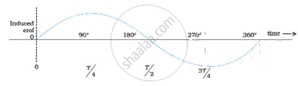
APPEARS IN
RELATED QUESTIONS
Electric field intensity in free space at a distance ‘r’ outside the charged conducting sphere of radius ‘R’ in terms of surface charge density ‘ a ’ is............................
(a)`sigma / in_0[R/r]^2`
(b)`in_0/sigma[R/r]^2`
(c)`R/r[sigma/in_0]^2`
(d)`R/sigma[r/in_0]^2`
When a bar magnet is pushed towards (or away) from the coil connected to a galvanometer, the pointer in the galvanometer deflects. Identify the phenomenon causing this deflection and write the factors on which the amount and direction of the deflection depends. State the laws describing this phenomenon.
Explain why, an electromagnet is called a temporary magnet.
The direction of current in the coil at one end of an electromagnet is clockwise. This end of the electromagnet will be:
(a) north pole
(b) east pole
(c) south pole
(d) west pole
In which of the following case does the electromagnetic induction occur?
The current is stopped in a wire held near a loop of wire .
Can a transformer work when it is connected to a D.C. source? Give a reason.
Fill in the blanks by writing (i) Only soft iron, (ii) Only steel, (iii) Both soft-iron and steel for the material of core and/or magnet.
D.C. motor ______.
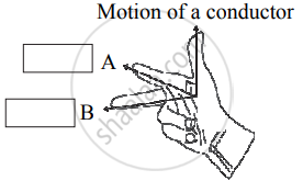
Observe the given figure of Fleming’s Right Hand Rule and write the labels of A and B correctly.
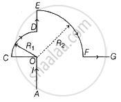
In the current carrying conductor (AOCDEFG) as shown, the magnetic induction at point O is ______.
(R1 and R2 are radii of CD and EF respectively. l = current in the loop, μ0 = permeability of free space)