Advertisements
Advertisements
Question
Explain the working of the transformer.
Advertisements
Solution
Principle:
The principle of a transformer is the mutual induction between two coils. That is, when an electric current passing through a coil changes with time, an emf is induced in the neighbouring coil.
Working:
- If the primary coil is connected to a source of alternating voltage, an alternating magnetic flux is set up in the laminated core.
- If there is no magnetic flux leakage, then the whole magnetic flux linked with primary coil is also linked with the secondary coif This means that rate at which magnetic flux changes through each turn is same for both primary and secondary coils.
- As a result of flux change, emf is induced in both primary and secondary coils. The emf induced in the primary coil εp is almost equal and opposite to the applied voltage υp and is given by
υp = εp = -Np `("d" Φ_"B")/"dt"` .....(1) - The frequency of alternating magnetic flux in the core is the same as the frequency of the applied voltage. Therefore, induced emf in secondary will also have the same frequency as that of applied voltage.
- The emf induced in the secondary coil eg is given by
εs = -Ns `("d" Φ_"B")/"dt"`
where Np and Ns are the number of turns in the primary and secondary coil, respectively. If the secondary circuit is open, then εs = υs where υs is the voltage across secondary coil.
υs εs = -Ns `("d" Φ_"B")/"dt"` .....(2)
From equation (1) and (2),
`"v"_"s"/epsilon_"s" = "N"_"s"/"N"_"p"` = K ....(3)
This constant K is known as voltage transformation ratio. For an ideal transformer,
Input power υp ip = Output power υsis
where iυp and is are the currents in the primary and secondary coil respectively. Therefore,
`"v"_"s"/"v"_"p" = "N"_"s"/"N"_"p" = "i"_"p"/"i"_"s"`
Equation (4) is written in terms of amplitude of corresponding quantities,
`"V"_"s"/"V"_"p" = "N"_"s"/"N"_"p" = "I"_"p"/"I"_"s"` = K ....(4)
(i) If Ns > Np ( or K > 1)
∴ Vs > Vp and Is < Ip.
This is the case of a step-up transformer in which voltage is decreased and the corresponding current is decreased.(ii) If Ns < Np (or K < 1)
∴ Vs < Vp and Is > Ip
This is a step-down transformer where voltage is decreased and the current is increased.
APPEARS IN
RELATED QUESTIONS
Derive an expression for ratio of e.m.f.s and currents in terms of number of turns in primary and secondary coil.
What type of current is transmitted from the power station?
The following diagram in Fig. 10.44 shows a coil X connected to a sensitive centre –zero galvanometer G and a coil P connected to a battery through a switch S.
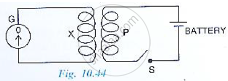
(a) Describe the observation when the switch S is (i) closed suddenly, (ii) then kept closed, (iii) finally opened.
(b) Name and state the law which explains the above observations.
A transformer is essentially an a.c. device. It cannot work on d.c. It changes alternating voltages or currents. It does not affect the frequency of a.c. It is based on the phenomenon of mutual induction. A transformer essentially consists of two coils of insulated copper wire having different numbers of turns and wound on the same soft iron core.
The number of turns in the primary and secondary coils of an ideal transformer is 2000 and 50 respectively. The primary coil is connected to a main supply of 120 V and secondary coil is connected to a bulb of resistance 0.6 Ω.
The value of voltage across the secondary coil is ______.
A step down transformer connected to an ac mains supply of 220 V is made to operate at 11 V, 44 W lamp. Ignoring power losses in the transformer, what is the current in the primary circuit?
The line that draws power supply to your house from street has ______.
- zero average current.
- 220 V average voltage.
- voltage and current out of phase by 90°.
- voltage and current possibly differing in phase `phi` such that `|phi| < pi/2`.
An ideal transformer converts 220 V a.c. to 3.3 kV a.c. to transmit a power of 4.4 kW. If primary coil has 600 turns, then alternating current in secondary coil is ______.
The self-inductance of a closely wound coil of 200 turns is 10 mH. Determine the value of magnetic flux through the cross-section of the coil when the current passing through the coil is 4 mA.
Explain why core of a transformer is always laminated.
On the basis of winding, what are the two types of transformers?
