Wavefront is defined as the locus of all the points in space that reach a particular distance by a propagating wave at the same instant.
A wave front is defined as a surface of constant phase.
Definition: Wavefront
A wavefront is a surface of constant phase.
Definition: Spherical Wave
If a point source emits waves uniformly in all directions, the locus of points which have the same amplitude and vibrate in the same phase is a sphere. This is known as a spherical wave.
Definition: Plane Wave
At a large distance from the source, a small portion of the spherical wave can be considered as a plane. This is known as a plane wave.
Definition: Interference of Waves
When two waves of the same frequency, wavelength and velocity move in the same direction, on superposition, they result in interference.
Definition: Fringe
A fringe is a bright or dark band formed on the screen due to constructive or destructive interference.
Definition: Interference of Light
Interference is the phenomenon in which light intensity is modified due to the superposition of two or more light waves.
Definition: Fringe Width
Fringe width is the distance between two consecutive bright fringes or two consecutive dark fringes.
Definition: Diffraction
Diffraction is the phenomenon of bending of light (or any wave) around the corners or edges of an obstacle or aperture, causing it to spread into the geometrical shadow region and produce alternate dark and bright regions.
Definition: Coherent Sources
“Two sources are said to be coherent, if they emit light waves having a sharply defined phase difference that remains constant with time.”
Definition: Optical Path
The optical path travelled by a light ray is the product of the refractive index of the medium and the actual distance travelled by light in that medium.
Definition: Diffraction of Light
The bending of light round the corners of the obstacles, or apertures, is called 'diffraction’.
Definition: Diffraction Pattern
“The intensity distribution upon the screen is called the ‘diffraction pattern’ of the aperture.”
Definition: Polaroid
Polaroid is a cheap commercial device for producing and detecting plane-polarised light.
Definition: Plane of Polarization
The plane perpendicular to the plane of the vibration and the electric field vector is called plane of polarization.
Definition: Plane of Vibration
The plane containing the electric field vectors of plane polarized light is called the plane of vibration.
Definition: Fresnel Diffraction
Diffraction observed when the source or screen (or both) are at finite distances from the obstacle, and the incident wavefront is spherical or cylindrical.
Definition: Interference
Interference is the phenomenon in which the intensity of light (or any wave) at a point becomes non-uniform due to the superposition of two or more coherent waves, resulting in regions of constructive and destructive interference.
Definition: Limit of Resolution
The minimum visual angle between two objects that can be just resolved by an instrument is called the limit of resolution.
Definition: Resolving Power of Telescope
The resolving power of a telescope is then defined as the reciprocal of the least angular separation between the objects that are just resolved.
Definition: Resolving Power
The ability of an optical instrument to distinguish two closely spaced objects as separate and distinct is called its resolving power.
Definition: Polarization by Scattering
Polarisation by scattering is the phenomenon in which unpolarized light becomes partially or completely plane polarised when it is scattered by small particles such as air molecules or dust particles.
Definition: Wave Optics
The branch of optics which uses the wave nature of light to explain the optical phenomena is called wave optics.
Definition: Unpolarized Light
Light in which the electric field vectors vibrate in all possible directions perpendicular to the direction of propagation.
Definition: Plane Polarized Light
Light in which the electric field vectors vibrate only in one particular direction perpendicular to the direction of propagation.
Definition: Polarizer
A material that allows only those light waves to pass whose electric field is along a particular direction (polarizing axis).
Defintiion: Diffraction of Light
Diffraction of light is the phenomenon in which light spreads into the geometrical shadow region when it passes around the edges of an obstacle or through a narrow aperture whose size is comparable to its wavelength.
Definition: Zero-Order Fringe
“The central white fringe formed when the path difference is zero for all wavelengths is called the zero-order fringe.”
Definition: Plane of Polarisation
The plane containing the direction of propagation of light and perpendicular to the plane of vibration is called the ‘plane of polarisation’.
Definition: Transverse Wave
A wave in which the vibrations of the particles of the medium are perpendicular to the direction of propagation.
Definition: Longitudinal Wave
A wave in which the vibrations of the particles of the medium are parallel to the direction of propagation.
Definition: Polarisation of Light
The phenomenon in which the vibrations of the electric field vector of light are restricted to a single direction in a plane perpendicular to the direction of propagation.
Definition: Fraunhofer Diffraction
Diffraction observed when the source and screen are at large distances from the diffracting element, so that the incident wavefront is plane.
Definition: Ray of Light
- The path along which light travels is called a ray of light.
- A ray is defined as the path of energy propagation in the limit of wavelength tending to zero.
Definition: Ray Optics or Geometrical Optics
- The study of optical phenomena under the assumption that it travels in a straight line as a ray is called ray optics or geometrical optics, as geometry is used in this study.
- The branch of optics in which one completely neglects the finiteness of the wavelength is called geometrical optics.
Definition: Principle of Superposition
When two or more waves travel simultaneously in a medium, the resultant displacement at each point of the medium at any instant is equal to the vector sum of the displacements produced by the two waves separately. This principle is called 'principle of superposition'.
Definition: Polariser
The first crystal which polarises the light wave is called ‘polariser'.
Definition: Analyser
The second crystal which examines the nature of the light emerging from the first crystal, whether it is polarised or not, is called the ‘analyser'.
Definition: Unpolarised Light
Unpolarised light is light in which the vibrations of the electric field vector occur in all possible directions in a plane perpendicular to the direction of propagation.
Definition: Plane Polarised Light
In plane polarised light, the vibrations of the electric vector E occur in a plane perpendicular to the direction of propagation of light, and are confined to a single direction in the plane (do not occur symmetrically in all possible directions).
Definition: Plane of Vibration
The plane containing the direction of vibration of the electric vector and the direction of propagation of light is called the 'plane of vibration'.
Definition: Wavefront
If we draw a surface in a medium such that all the medium particles lying in the surface are in the same phase of oscillation, then the surface is called a 'wavefront'.
Definition: Interference of Light
The redistribution of light intensity due to the superposition of two light waves is called 'interference of light'.
Definition: Incoherent Sources
“If the phase difference between two light waves arriving at a point varies with time in a random way, the wave-sources are said to be incoherent.”
Formula: Fringe Width (β)
\[\beta=\frac{\lambda D}{d}\]
Formula: Angular fringe width (α)
\[\alpha=\frac{\beta}{D}=\frac{\lambda}{d}\]
Formula: Distance between n-th bright and m-th dark
\[x_n-x_m=\left[n-\frac{(2m-1)}{2}\right]\beta\]
Formula: Position of m-th dark fringe
\[\begin{array} {cc} & x_m=\frac{(2m-1)\lambda D}{2d} \end{array}\]
Formula: Position of n-th bright fringe
\[\begin{array} {c}x_n=\frac{n\lambda D}{d}=n\beta \end{array}\]
Formula: Average Intensity of Interference Pattern
Iav = \[\frac{I_{\max}+I_{\min}}{2}\] = K(a12 + a22)
Formula: Variation of Wavelength in Media
λw = \[\frac {λ}{n}\]
Formula: Single Slit Diffraction
e sin θ = ±mλ (m=1,2,3,…)
Formula: Optical Path
\[t=\frac{D}{v}=\frac{D}{c/n}=\frac{nD}{c}\]
OR
d = n D.
Formula: Subsidiary Maxima
e sin θ = \[\frac{(2m+1)\lambda}{2}\]
Formula: Fraunhofer Diffraction at a Single Slit
\[a\sin\theta=\pm\left(n+\frac{1}{2}\right)\lambda\]
Formula: Width of the Central Bright Fringe
\[W_{c}=2y_{1d}=2W=2\left(\frac{\lambda D}{a}\right)\]
State the law of refraction.
The law of refraction is called Snell’s law.
Snell’s law states that,
- The incident ray, refracted ray and normal to the refracting surface are all coplanar (i.e., lie in the same plane).
- The ratio of the angle of incidence i in the first medium to the angle of reflection r in the second medium is equal to the ratio of the refractive index of the second medium n2 to that of the refractive index of the first medium n1.
`(sin "i")/(sin "r") = "n"_2/"n"_1`
With the help of a diagram, show how a plane wave is reflected from a surface. Hence, verify the law of reflection.
According to the laws of reflection:
- At the point of incidence, the incident rays, reflected rays, and normal to the reflecting surface all lie in the same plane.
- On opposing sides of the normal are the incident and reflected rays.
- The angle of incidence and the angle of reflection are the same. i.e., ∠i = ∠r.
Explanation:
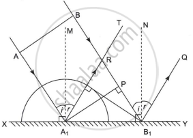
Reflection of light
XY: Plane reflecting surface
AB: Plane wavefront
RB1: Reflecting wavefront
A1M, B1N: Normal to the plane
∠AA1M = ∠BB1N = ∠i = Angle of incidence
∠TA1M = ∠QB1N = ∠r = Angle of reflection
A plane wavefront AB is advancing obliquely towards the plane reflecting surface XY. The AA1 and BB1 are incident rays.
When ‘A’ reaches XY at A1, then the ray at ‘B’ reaches point ‘P’, and it has to cover the distance PB1 to reach the reflecting surface XY.
Let ‘t’ be the time required to cover the distance PB1. During this time interval, secondary wavelets are emitted from A1 and will spread over a hemisphere of radius A1R, in the same medium. The distance covered by secondary wavelets to reach from A1 to R in time t is the same as the distance covered by primary waves to reach from P to B1. Thus, A1R = PB1 = ct.
All other rays between AA1 and BB1 will reach XY after A1 and before B1. Hence, they will also emit secondary wavelets of decreasing radii.
The surface touching all such hemispheres is RB1 which is the reflected wavefront, bounded by reflected rays A1R and B1Q.
Draw A1M ⊥ XY and B1N ⊥ XY.
Thus, the angle of incidence is ∠AA1M = ∠BB1N = i, and the angle of reflection is ∠MA1R = ∠NB1Q = r.
∠RA1B1 = 90 − r
∠PB1A1 = 90 − i
In ΔA1RB1 and ΔA1PB1
∠A1RB1 = ∠A1PB1
A1R = PB1 ...(Reflected waves travel an equal distance in the same medium in equal time.)
A1B1 = A1B1 ....(Common side)
∴ ΔA1RB1 ≅ ΔA1PB1
∴ ∠RA1B1 = ∠PB1A1
∴ 90 − r = 90 − i
∴ i = r
Also from the figure, it is clear that incident rays, reflected rays, and normal lie in the same plane.
This explains the laws of reflection of light from a plane reflecting surface on the basis of Huygen’s wave theory.
Frequency, wavelength, and speed of light do not change after reflection. If reflection takes place from a denser medium, then the phase changes by π radians.
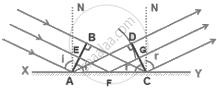
AB = Incident wavefront
CD = Reflected wavefront
XY = Reflecting surface
If c be the speed of light and t be the time taken by light to go from B to C or A to D or E to G through F, then
t = `(EF)/C + (FG)/C`
= `(AF sin i)/C + (FC sin r)/C`
= `(AC sin r + AF(sin i - sin r))/C`
For rays of light from different parts of the incident wavefront, the values of AF are different. But light from different points of the incident wavefront should take the same time to reach the corresponding points on the reflected wavefront.
So, ‘t’ should not depend upon AF.
This is possible only if sin i – sin r = 0.
i.e., sin i = sin r
⇒ i = r
Hence proved.
Law: Principle of Superposition of Waves
When two or more pulses overlap, the resultant displacement is the algebraic sum of the displacements due to each pulse.
Law: Brewster’s Law
Statement
When unpolarised light is incident on the surface of a transparent medium at a particular angle, the reflected light becomes completely plane-polarised.
This angle of incidence is called the polarising angle or Brewster’s angle (ip).
According to Brewster’s Law, the refractive index n of the medium is related to the polarising angle by:
n = tan ip
Explanation / Proof
Consider unpolarised light incident on the surface of a transparent medium (e.g., air–glass interface) at the polarising angle ip.
Let:
- ip = angle of incidence (polarising angle)
- r = angle of refraction
- n = refractive index of the second medium w.r.t. the first
From Snell’s law:
n = \[\frac {sin i_p}{sin r}\]
From Brewster’s law:
n = tan ip = \[\frac {sin i_p}{cos i_p}\]
Equating the two expressions for n:
\[\frac{\sin i_p}{\sin r}=\frac{\sin i_p}{\cos i_p}\]
⇒ sin r = cos ip
⇒ sin r = sin(90∘ − ip)
⇒ r = 90∘ − ip
Hence,
ip + r = 90∘
Therefore, the reflected ray and refracted ray are mutually perpendicular.
Conclusion
- Brewster’s law establishes a direct relation between refractive index and polarising angle:
n = tan ip
- At the polarising angle:
Reflected light is completely plane-polarised
Reflected and refracted rays are perpendicular to each other
- This law explains the polarisation of light by reflection and is a strong confirmation of the transverse nature of light waves
Law: Law of Malus
Statement
The intensity of plane-polarised light transmitted through an analyser is directly proportional to the square of the cosine of the angle between the transmission axes of the polariser and the analyser.
I = I0 cos2θ
Explanation / Proof
- Let a beam of completely plane-polarised light of amplitude aaa fall on an analyser.
- Let θ be the angle between the transmission axes of the polariser and analyser.
- The amplitude of light along the analyser’s axis is a cos θ.
- Since intensity ∝ (amplitude)2,
I = K(a cos θ)2 = K a2 cos2 θ
- If I0 = Ka2 is the incident intensity, then:
I = I0 cos2 θ
Conclusion
Thus, the transmitted intensity depends on the relative orientation of the polariser and analyser and follows the relation
I = I0 cos2 θ
This relation is known as the Law of Malus.
Law: Brewster’s Law
Statement
When unpolarized light is incident on a transparent surface at a particular angle (called Brewster’s angle), the reflected light is completely plane polarised.
At this angle, the reflected and refracted rays are perpendicular to each other.
tanθB = \[\frac {n_2}{n_1}\]
where
θB = Brewster’s angle
n1, n2 = refractive indices of the two media
Proof
At Brewster’s angle,
θB + r = 90∘
From Snell’s law:
n1 sin θB = n2 sin r
Since r = 90∘ − θB,
n1 sinθB = n2 cosθB
tan θB = \[\frac {n_2}{n_1}\]
Conclusion
At Brewster’s angle, the reflected light is completely plane polarized and the reflected and refracted rays are mutually perpendicular.
Law: Huygens' Principle
"Each point on a wavefront acts as a secondary source of light emitting secondary light waves called wavelets in all directions which travel with the speed of light in the medium. The new wavefront can be obtained by taking the envelope of these secondary wavelets travelling in the forward direction and is thus, the envelope of the secondary wavelets in forward direction. The wavelets travelling in the backward direction are in effective".
Law: Laws of Reflection
First Law of Reflection:
i = r
The angle of incidence is equal to the angle of reflection.
Second Law of Reflection:
The incident ray, reflected ray, and the normal at the point of incidence lie in the same plane.
Law: Malus’ Law
I2 = I1cos2θ
It gives the intensity of plane polarized light after passing through a second polarizer, where θ is the angle between the axes of the two polarizers.
Principle: Huygens' Wave Theory
Huygens proposed a geometrical construction to explain the propagation of a wavefront in the medium and determined the position of the wavefront after any interval of time. This is known as 'Huygens' principle' and may be stated as follows :
- Every particle of the medium situated on the wavefront acts as a new wave-source from which fresh waves originate. These waves are called ‘secondary wavelets'.
- The secondary wavelets travel in the medium in all directions with the speed of the original wave (light) in the medium.
- The envelope of the secondary wavelets in the forward
direction at any instant gives the new wavefront at that instant.
Key Points: Concept of Wave Optics
- Wave optics studies the wave nature of light.
- Newton supported the corpuscular theory of light.
- Huygens proposed the wave theory in 1678.
- Young's 1801 interference experiment supported the wave model.
- Maxwell explained light as an electromagnetic wave.
- Geometrical optics treats light as rays.
- Wave optics includes Huygens' principle, interference, diffraction, and polarisation.
Ky Points: Principle of Superposition of Waves
| Feature |
Constructive Interference |
Destructive Interference |
| Phase Difference (φ) |
\[0,2\pi,4\pi,\ldots\] |
\[\pi,3\pi,5\pi,\ldots\] |
| Path Difference |
\[n\lambda\] |
\[(2n+1)\frac{\lambda}{2}\] |
| Nature |
Waves reinforce |
Waves cancel |
| Amplitude |
Maximum |
Minimum |
| Intensity |
Maximum (bright) |
Minimum (dark) |
| Result |
Crest + Crest |
Crest + Trough |
Key Points: Refraction of Light at a Plane Boundary Between Two Media
- Refraction at a plane boundary can be explained using Huygens’ principle and secondary wavelets.
- When light enters a denser medium, its speed decreases and the wavefronts become closer.
- The refracted image is not laterally inverted, but it appears bent (broken) at the boundary for oblique incidence.
- The wavelength of light changes when it enters a different medium; it decreases in a denser medium.
- The frequency remains unchanged while passing from one medium to another.
Key Points: Reflection of a Plane Wave at a Plane Surface
- According to Huygens’ principle, each point on the incident plane wavefront acts as a source of secondary wavelets, whose forward envelope gives the reflected wavefront.
- The reflected wavefront is obtained by drawing a common tangent to the secondary wavelets, showing that reflection follows wavefront construction.
- Using this construction, the laws of reflection are obtained:
angle of incidence equals angle of reflection (i = r), and
incident ray, reflected ray, and normal lie in the same plane.
Key Points: Plane Wavefront: Reflection and Refraction
| Incident Wavefront |
Medium |
Nature of Wavefront after Reflection / Refraction |
| Plane |
Plane reflecting surface |
Plane |
| Plane |
Plane refracting surface |
Plane |
| Plane |
Prism |
Plane |
| Plane |
Convex lens |
Spherical (converging) |
| Plane |
Concave lens |
Spherical (diverging) |
| Plane |
Concave mirror |
Spherical (converging) |
Key Points: Refraction of a Plane Wave at a Plane Surface
- Refraction of a plane wavefront can be explained using Huygens’ principle by constructing secondary wavelets in the second medium.
- The refracted wavefront is the forward envelope of secondary wavelets formed in the second medium.
- Rays are normal to wavefronts, so the angles between wavefronts give the angles of incidence and refraction.
- Huygens’ construction leads to Snell’s law, showing that sini/sinr\sin i / \sin rsini/sinr is constant for two given media.
- Wave theory proves that light travels slower in optically denser media, a result confirmed by Foucault’s experiment.
Key Points: Wavefront
- In a homogeneous isotropic medium, wavefronts are always perpendicular to the direction of wave propagation.
- Rays are drawn normal to the wavefront and indicate the direction of propagation of the wave.
- A point source produces spherical wavefronts, with rays spreading radially outward.
- A plane wavefront consists of parallel rays, while a linear source produces cylindrical wavefronts.
Key Points: Interference of Light Waves
- In Young’s double-slit experiment, two narrow slits act as coherent sources, producing an interference pattern of alternate bright and dark fringes on a distant screen.
- Bright fringes are formed by constructive interference when crests meet crests or troughs meet troughs (same phase), resulting in maximum intensity.
- Dark fringes are formed by destructive interference when crests meet troughs (opposite phase), resulting in zero or minimal intensity.
- Fringe width depends on wavelength: red light produces wider fringes than blue light, supporting the wave nature of light.
key Points: Nature of Light
- Corpuscular theory (Newton): Light consists of particles called corpuscles that travel in straight lines; it explains reflection but fails to account for the correct speed in denser media.
- Wave theory (Huygens): Light behaves as a wave and accounts for reflection, refraction, interference, diffraction, and polarisation.
- Wave theory correctly states that the speed of light is lower in denser media, so light bends towards the normal.
- Geometrical (ray) optics studies light as straight-line rays; wave optics explains light using its wave nature.
- Dual nature of light: Light exhibits both particle nature (photons) and wave nature under different conditions.
Key Points: Conditions for Sustained Interference of Light Waves
- Sources must be coherent — they should maintain a constant phase difference for sustained interference.
- The same frequency (monochromatic light) is required; different frequencies cause intensity fluctuations.
- The principle of superposition must apply for interference to occur.
- The separation between sources should be small to obtain sufficiently wide and visible fringes.
- Screen distance should be set to a large value to increase fringe width and visibility.
- Amplitudes of waves should be equal or nearly equal for maximum contrast between fringes.
- Sources (slits) should be narrow to prevent fringe overlap.
- Monochromatic light is essential to avoid mixing and loss of fringe clarity.
Key Points: Fringe Formation in Young’s Double-Slit Experiment
- A central bright fringe is formed at point O, where the path difference is zero (S1O = S2O).
- Bright fringes occur when path difference = mλ; dark fringes occur when path difference = (2m − 1)λ/2.
- Positions of bright fringes are given by
xm = \[\frac {mDλ}{d}\]
and dark fringes lie exactly midway between bright fringes.
- Fringe width (β) is the distance between two successive bright or dark fringes and is the same for all fringes:
β = \[\frac {Dλ}{d}\]
- Fringe width increases with wavelength; hence, red light produces wider fringes than blue light.
Key Points: Polarisation of Light by Refraction
- At the polarising angle, the reflected light becomes completely plane polarised, while the refracted light is partially polarised.
- Using a pile of parallel plates, repeated refraction and reflection produce almost completely plane-polarised light with vibrations parallel to the plane of incidence.
Key Points: Fraunhofer's Diffraction
- A single-slit diffraction pattern consists of a bright central band with alternating dark and faint bands on either side.
- The central maximum is the brightest and widest, and most of the incident light is concentrated in it.
- Diffraction becomes more prominent when the slit width is small, especially when it is comparable to the wavelength of light.
- Red light spreads more than blue light in diffraction, showing that diffraction depends on wavelength.
- Narrowing the slit increases the width of the central maximum, while widening the slit reduces diffraction and makes light propagation nearly rectilinear.
Key Points: Polaroid
- Unpolarised light has electric vectors vibrating randomly in all directions perpendicular to the direction of propagation.
- When unpolarised light passes through an ideal polariser/analyser, the maximum transmitted intensity is 50% of the incident light.
- A Polaroid transmits only those components of light whose electric vectors vibrate parallel to its polarising direction.
- If two Polaroids are parallel, light transmitted by the first passes through the second.
- If two Polaroids are crossed (90°), no light is transmitted, showing complete extinction.
Key Points: Uses of Polaroids
- Polaroids are used to reduce glare from shiny surfaces like wet roads and glass.
- Polarised sunglasses cut off horizontally polarised reflected light and reduce eye strain.
- Polaroids are used in car headlights and windscreens to prevent dazzling from opposite vehicles.
- Crossed Polaroids in cars block headlight glare while allowing safe visibility.
- Polaroids are fitted in microscopes to reduce glare and view minute particles clearly.
- Polaroids in camera lenses help take clear photographs of clouds by reducing scattered light.
- Polaroids are used in trains and aeroplanes to control light intensity through windows.
- Polaroid glasses are used to view three-dimensional (3D) images.
- When a Polaroid is rotated, unpolarised light shows no change in intensity.
- On rotation, plane-polarised light shows maximum and zero intensity, while partially polarised light never becomes zero.
Key Points: Light Sources and Wavefronts
- Primary sources emit their own light (e.g., the Sun, stars, a bulb); secondary sources reflect or scatter light (e.g., the Moon, planets).
- A wavefront is the locus of all points having the same phase at a given instant of time.
- The direction of propagation of light is perpendicular to the wavefront (along the rays).
- A point source produces spherical wavefronts; far from the source, they appear as plane wavefronts.
- A line source produces cylindrical wavefronts; the wave speed equals the speed at which the wavefront moves.
Key Points: Resolving Power
- Resolution depends on diffraction effects caused by the optical instrument's aperture.
- According to Rayleigh’s criterion, two objects are just resolved when the central maximum of one diffraction pattern coincides with the first minimum of the other.
- For a single slit (linear objects), the limit of resolution:
dθ = \[\frac {λ}{a}\]
- In a microscope, resolving power increases with numerical aperture (N.A. = n sin α) and decreases with wavelength:
R ∝ \[\frac {N.A.}{λ}\]
- For self-luminous point objects (microscope):
a = \[\frac {0.61λ}{N.A.}\]
- For a telescope, angular resolution is:
θ = \[\frac {1.22λ}{D}\]
where D is the aperture diameter.
- Resolving power improves when:
Wavelength is smaller
Aperture diameter is larger
The numerical aperture is higher
Key Points: Light as a Wave
- Light is a transverse electromagnetic wave consisting of oscillating electric and magnetic fields perpendicular to each other and to the direction of propagation.
- Light does not require a medium and travels in a vacuum at the speed of light
c = 3 × 10⁸ m/s
Refractive index n = \[\frac {c}{v}\]
- Visible light has wavelengths from 400–700 nm; different wavelengths produce different colours and cause dispersion (spectrum formation).
Key Points: Reflection of Light at a Plane Surface
- Reflection at a plane surface can be explained using Huygens’ principle and secondary wavelets.
- The reflected wavefront is formed as the envelope of secondary wavelets produced at the reflecting surface.
- The distance travelled by incident and reflected waves in the same time is equal (AE = BC = vT).
- The size of the image formed by a plane mirror is equal to the size of the object.
- The image formed in a plane mirror shows lateral reversal (right and left are interchanged).
Key Points: Interference
- Coherent sources emit waves of the same frequency with a constant phase difference.
- In Young’s double slit experiment, two coherent sources are obtained from a single source.
- Condition for constructive interference:
Path difference Δl = nλ
- Condition for destructive interference:
Path difference Δl = (n − \[\frac {1}{2}\])λ
- Position of bright fringe:
yn = \[\frac {nλD}{d}\]
- Fringe width:
W = \[\frac {λD}{d}\]
(Bright and dark fringes are equally spaced.)
- For a clear and steady interference pattern:
Sources must be coherent, monochromatic, of nearly equal amplitude, and slits must be narrow with D ≫ d.
Key Points: Constructive and Destructive Interference
- Interference occurs when waves from two coherent sources superpose, and the resulting intensity depends on the phase difference between them.
- Resultant intensity at a point is given by
I = I1 + I2 + 2\[\sqrt {I_1 I_2}\] cos ϕ,
showing its dependence on phase difference ϕ\phiϕ.
- Constructive interference occurs when the waves meet in phase, i.e., ϕ = 2mπ or path difference x = mλ, resulting in maximum intensity.
- Destructive interference occurs when the waves meet in opposite phase, i.e. ϕ = (2m−1)π or path difference x = (2m − 1)\[\frac {λ}{2}\], giving minimum intensity.
- Alternate bright and dark fringes appear on the screen, producing an interference pattern due to the continuous variation in the path difference.
Key Points: Polarisation by Scattering
- Scattering of light occurs when white light passes through very small particles, such as dust or air molecules.
- The scattered light seen perpendicular to the incident beam appears blue.
- Light scattered at right angles is plane-polarised, as shown using an analyser.
