Advertisements
Advertisements
प्रश्न
Two circular loops of equal radii are placed coaxially at some separation. The first is cut and a battery is inserted in between to drive a current in it. The current changes slightly because of the variation in resistance with temperature. During this period, the two loops _______________ .
पर्याय
attract each other
repel each other
do not exert any force on each other
attract or repel each other depending on the sense of the current
Advertisements
उत्तर
attract each other
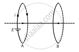
Consider loops A and B placed coaxially as above. Let the direction of the current in loop A be clockwise when a battery is connected to it. According to the right-hand screw rule, the direction of the magnetic field due to this current will be towards the left. Now, the current through this loop will decrease with time due to an increase in resistance with temperature. So, the magnetic field due to this current will also decrease with time. This changing current will induce a current in loop B. Now, according to Lenz's law, the direction of the induced current in loop B will be such that it will oppose the decrease in the magnetic field due to loop A. Hence, current will be induced in a clockwise direction in loop B. Also, because the direction of the currents in the loops is the same, they will attract each other.
APPEARS IN
संबंधित प्रश्न
Describe a simple experiment (or activity) to show that the polarity of emf induced in a coil is always such that it tends to produce a current which opposes the change of magnetic flux that produces it.
What is the direction of induced currents in metal rings 1 and 2 when current I in the wire is increasing steadily?
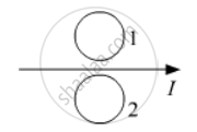
Predict the direction of induced current in metal rings 1 and 2 when current I in the wire is steadily decreasing?
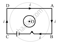
Consider the situation shown in figure. If the closed loop is completely enclosed in the circuit containing the switch, the closed loop will show _______________ .
Lenz’s law is a consequence of the law of conservation of ______.
2 A 40 kg boy whose legs are 4 cm in area and 50 cm long falls through a height of 2 m without breaking his leg bones. If the bones can withstand stress of 0.9 x 10⁸ N/m2. The Young's modulus for the material of the bone is ______.
A bar magnet is dropped through a copper ring acceleration of magnet is
A solenoid is connected to a battery so that a steady current flows through it. If an iron core is inserted into the solenoid, will the current increase or decrease? Explain.
A long solenoid ‘S’ has ‘n’ turns per meter, with diameter ‘a’. At the centre of this coil we place a smaller coil of ‘N’ turns and diameter ‘b’ (where b < a). If the current in the solenoid increases linearly, with time, what is the induced emf appearing in the smaller coil. Plot graph showing nature of variation in emf, if current varies as a function of mt2 + C.
Predict the direction of induced current in the situation described by the following figure.
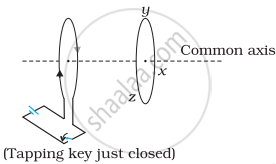
Use Lenz’s law to determine the direction of induced current in the situation described by the figure.
A circular loop being deformed into a narrow straight wire.

When the N-pole moves towards the coil, what happens to the flux and galvanometer?
What is observed when the magnet is held stationary near the coil?
When the N-pole moves away from the coil, what happens to the flux and galvanometer?
When the N-pole moves away from the coil, which induced current direction and near-face pole are observed?
What would happen to the magnet if an induced South pole attracted an approaching N-pole without external effort?
How does an induced field oppose a decrease in magnetic flux?
What happens as the rate of change of magnetic flux becomes greater?
