Advertisements
Advertisements
प्रश्न
The plates of a parallel-plate capacitor are given equal positive charges. What will be the potential difference between the plates? What will be the charges on the facing surfaces and on the outer surfaces?
Advertisements
उत्तर
It is given that the plates of the capacitor have the same charges. In other words, they are at the same potential, so the potential difference between them is zero.
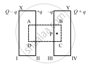
Let us consider that the charge on face II is q so that the induced charge on face III is `-q` and the distribution is according to the figure.
Now, if we consider Gaussian surface ABCD, whose faces lie inside the two plates, and calculate the field at point P due to all four surfaces, it will be
`E_1 = (Q-q)/(2∈_0A)`
`E_2 = (q)/(2∈_0A)`
`E_3 = (q)/(-2∈_0A)`
`E_4 = (Q+q)/(2∈_0A)` (It is `-Ve` because point P is on the left side of face IV. )
Now, as point P lies inside the conductor, the total field must be zero.
`therefore` E1 + E2 + E3 + E4 = 0
Or
`Q-q+q-q+Q+q = 0`
∴ q = 0
Hence, on faces II and III, the charge is equal to zero; and on faces I and IV, the charge is Q.
Thus, it seems that the whole charge given is moved to the outer surfaces, with zero charge on the facing surfaces.
APPEARS IN
संबंधित प्रश्न
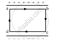
The electric field inside a parallel plate capacitor is E. Find the amount of work done in moving a charge q over a closed loop a b c d a.
Three capacitors of capacitances 2 pF, 3 pF and 4 pF are connected in parallel. Determine the charge on each capacitor if the combination is connected to a 100 V supply.
Figure 4 below shows a capacitor C, an inductor L and a resistor R, connected in series
to an a.c. supply of 220 V
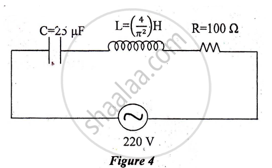
Calculate:
1) The resonant frequency of the given CLR circuit.
2) Current flowing through·the circuit.
3) Average power consumed by the circuit.
Suppose a charge +Q1 is given to the positive plate and a charge −Q2 to the negative plate of a capacitor. What is the "charge on the capacitor"?
Each plate of a parallel plate capacitor has a charge q on it. The capacitor is now connected to a batter. Now,
(a) the facing surfaces of the capacitor have equal and opposite charges
(b) the two plates of the capacitor have equal and opposite charges
(c) the battery supplies equal and opposite charges to the two plates
(d) the outer surfaces of the plates have equal charges
The plates of a capacitor are 2⋅00 cm apart. An electron-proton pair is released somewhere in the gap between the plates and it is found that the proton reaches the negative plate at the same time as the electron reaches the positive plate. At what distance from the negative plate was the pair released?
Two parallel plate capacitors X and Y, have the same area of plates and same separation between plates. X has air and Y with dielectric of constant 2, between its plates. They are connected in series to a battery of 12 V. The ratio of electrostatic energy stored in X and Y is ______.
Three capacitors each of 4 µF are to be connected in such a way that the effective capacitance is 6µF. This can be done by connecting them:
Three different capacitors are·connected in series. Then:-
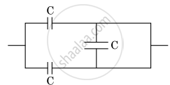
The equivalent capacitance of the combination shown in the figure is ______.
Two charges q1 and q2 are placed at (0, 0, d) and (0, 0, – d) respectively. Find locus of points where the potential a zero.
The capacitors, each of 4 µF are to be connected in such a way that the effective capacitance of the combination is 6 µF. This can be achieved by connecting ______.
What is the equivalent capacitance of \[n\] identical capacitors, each with capacitance \[C\], connected in series?
For two capacitors in series, which expression gives the voltage across the first capacitor?
For two capacitors in series, which expression gives the voltage across the second capacitor?
In a series combination, which capacitor has the larger voltage drop?
What is the voltage relationship for capacitors in parallel?
Compared with the individual capacitors in a parallel combination, how large is the equivalent capacitance?
Which relation gives the charge on one capacitor in a parallel combination when the common voltage is \[V\]?
Which expressions give the energy stored in series and parallel combinations, respectively?
