Advertisements
Advertisements
प्रश्न
The dielectric strength of air is 3.0 × 10⁶ V/m. A parallel-plate air-capacitor has area 20 cm2 and plate separation 0.10 mm. Find the maximum rms voltage of an AC source that can be safely connected to this capacitor.
Advertisements
उत्तर
Given:
Area of parallel-plate air-capacitor, A = 20 cm2
Separation between the plates, d = 0.1 mm
Dielectric strength of air, E= 3 × 10⁶ V/m
E = `V/d`,
where V = potential difference across the capacitor
`therefore V = Ed`
`= 3xx10^6xx0.1xx10^-3`
`= 3xx10^2=300 V`
Thus, peak value of voltage is 300 V.
Maximum rms value of voltage `(V_{rms})` is given by,
`V_{rms} = V_0 /sqrt2`
= `300/sqrt2 = 212 V`
APPEARS IN
संबंधित प्रश्न
A 2 µF capacitor, 100 Ω resistor and 8 H inductor are connected in series with an AC source.
(i) What should be the frequency of the source such that current drawn in the circuit is maximum? What is this frequency called?
(ii) If the peak value of e.m.f. of the source is 200 V, find the maximum current.
(iii) Draw a graph showing variation of amplitude of circuit current with changing frequency of applied voltage in a series LRC circuit for two different values of resistance R1 and R2 (R1 > R2).
(iv) Define the term 'Sharpness of Resonance'. Under what condition, does a circuit become more selective?
A current i1 = i0 sin ωt passes through a resistor of resistance R. How much thermal energy is produced in one time period? A current i2 = −i0 sin ωt passes through the resistor. How much thermal energy is produced in one time period? If i1 and i2 both pass through the resistor simultaneously, how much thermal energy is produced? Is the principle of superposition obeyed in this case?
A transformer is designed to convert an AC voltage of 220 V to an AC voltage of 12 V. If the input terminals are connected to a DC voltage of 220 V, the transformer usually burns. Explain.
An AC source producing emf ε = ε0 [cos (100 π s−1)t + cos (500 π s−1)t] is connected in series with a capacitor and a resistor. The steady-state current in the circuit is found to be i = i1 cos [(100 π s−1)t + φ1) + i2 cos [(500π s−1)t + ϕ2]. So,
An AC source is rated 220 V, 50 Hz. The average voltage is calculated in a time interval of 0.01 s. It
A bulb rated 60 W at 220 V is connected across a household supply of alternating voltage of 220 V. Calculate the maximum instantaneous current through the filament.
Suppose the initial charge on the capacitor is 6 mC. What is the total energy stored in the circuit initially? What is the total energy at later time?
If circuit containing capacitance only, the current ______.
Explain why the reactance provided by a capacitor to an alternating current decreases with increasing frequency.
Define Capacitive reactance.
An iron cored coil is connected in series with an electric bulb with an AC source as shown in figure. When iron piece is taken out of the coil, the brightness of the bulb will ______.
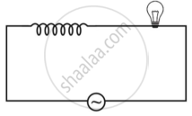
In an ac circuit an alternating voltage e = 200\[\sqrt 2\] sin100t volts is connected to capacitor of capacity 1 µF. The r.m.s. value of the current in the circuit is ______.
When an AC voltage of 220 V is applied to the capacitor C ______.
What is the applied voltage at any instant when a capacitor is connected to an AC source?
Which relation expresses that the voltage across the capacitor equals the applied voltage?
What happens to the current after a capacitor has charged from a DC source?
How does a lamp in series with a capacitor behave when connected to an AC source?
What is the capacitive reactance of a \[15.0\,\mu\mathrm{F}\] capacitor connected to a \[50\,\mathrm{Hz}\] source?
What is the peak current when the rms current is \[1.04\,\mathrm{A}\]?
