Advertisements
Advertisements
प्रश्न
A device Y is connected across an AC source of emf e = e0 sin ωt. The current through Y is given as i = i0 sin (ωt + π/2).
- Identify the device Y and write the expression for its reactance.
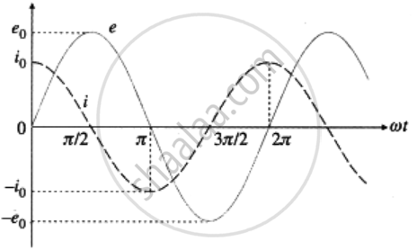
- Draw graphs showing a variation of emf and current with time over one cycle of AC for Y.
- How does the reactance of the device Y vary with the frequency of the AC? Show graphically.
- Draw the phasor diagram for device Y.
Advertisements
उत्तर
1. The device Y is a capacitor. Its reactance is `"X"_"C" = 1/(omega"C")`, where ω is the angular frequency of the applied emf and C is the capacitance of the capacitor.
2.
3. `"X"_"C" = 1/(omega"C") = 1/(2pi"fC")`. Thus `"X"_"C" prop 1/"f"`, where f is the frequency of AC.
Suppose C = `(1000/(2pi))`pF
For f = 100 Hz, XC = 1 × 10⁷ Ω = 10 M Ω;
for f = 200 Hz, XC = 5 M Ω;
for f = 300 Hz, XC = `10/3` M Ω;
for f = 400 Hz, XC = 2.5 M Ω
for f = 500 Hz, XC = 2 M Ω and so on.
(1 M Ω = 106 Ω)
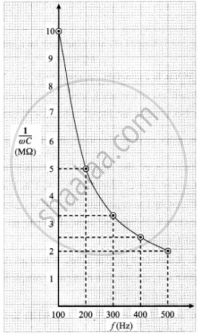
Variation of `1/(omega"C")` with f
4. Phasor diagram for a purely capacitive circuit
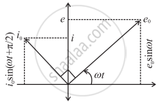
The phasor representing the peak emf (e0) makes an angle wt in an anticlockwise direction with respect to the horizontal axis. As the current leads the voltage by 90°, the phasor representing the peak current (i0) is turned 90° anticlockwise with respect to the phasor representing emf e0. The projections of these phasors on the vertical axis give instantaneous values of e and i.
APPEARS IN
संबंधित प्रश्न
Show that the current leads the voltage in phase by π/2 in an AC circuit containing an ideal capacitor ?
When an AC source is connected to a capacitor, there is a steady-state current in the circuit. Does it mean that the charges jump from one plate to the other to complete the circuit?
A current i1 = i0 sin ωt passes through a resistor of resistance R. How much thermal energy is produced in one time period? A current i2 = −i0 sin ωt passes through the resistor. How much thermal energy is produced in one time period? If i1 and i2 both pass through the resistor simultaneously, how much thermal energy is produced? Is the principle of superposition obeyed in this case?
Is energy produced when a transformer steps up the voltage?
An AC source producing emf ε = ε0 [cos (100 π s−1)t + cos (500 π s−1)t] is connected in series with a capacitor and a resistor. The steady-state current in the circuit is found to be i = i1 cos [(100 π s−1)t + φ1) + i2 cos [(500π s−1)t + ϕ2]. So,
The peak voltage of a 220 V AC source is
An AC source is rated 220 V, 50 Hz. The average voltage is calculated in a time interval of 0.01 s. It
The AC voltage across a resistance can be measured using
A bulb rated 60 W at 220 V is connected across a household supply of alternating voltage of 220 V. Calculate the maximum instantaneous current through the filament.
A transformer has 50 turns in the primary and 100 in the secondary. If the primary is connected to a 220 V DC supply, what will be the voltage across the secondary?
Compare resistance and reactance.
Average power supplied to a capacitor over one complete cycle is ______.
If circuit containing capacitance only, the current ______.
A.C. power is transmitted from a power house at a high voltage as ______.
When an ac voltage of 220 V is applied to the capacitor C, then ______.
A capacitor has capacitance C and reactance X, if capacitance and frequency become double, then reactance will be ______.
When an AC voltage of 220 V is applied to the capacitor C ______.
- the maximum voltage between plates is 220 V.
- the current is in phase with the applied voltage.
- the charge on the plates is in phase with the applied voltage.
- power delivered to the capacitor is zero.
A device ‘X’ is connected to an a.c source. The variation of voltage, current and power in one complete cycle is shown in figure.
- Which curve shows power consumption over a full cycle?
- What is the average power consumption over a cycle?
- Identify the device ‘X’.

Define Capacitive reactance.
A resistor of 50 Ω, a capacitor of `(25/pi)` µF and an inductor of `(4/pi)` H are connected in series across an ac source whose voltage (in volts) is given by V = 70 sin (100 πt). Calculate:
- the net reactance of the circuit
- the impedance of the circuit
- the effective value of current in the circuit.
An AC source is connected to a capacitor C. Due to decrease in its operating frequency ______.
A 40 µF capacitor is connected to a 200 V. 50 Hz ac supply. The rms value of the current on the circuit is, nearly ______.
In an ac circuit an alternating voltage e = 200\[\sqrt 2\] sin100t volts is connected to capacitor of capacity 1 µF. The r.m.s. value of the current in the circuit is ______.
In an alternating current circuit consisting of elements in series, the current increases on increasing the frequency of supply. Which of the following elements are likely to constitute the circuit?
When an AC voltage of 220 V is applied to the capacitor C ______.
The resistance of a coil for d.c. is 5 Ω. In a.c., the resistance will ______.
