Advertisements
Advertisements
प्रश्न
Find out the phase relationship between voltage and current in a pure inductive circuit.
Advertisements
उत्तर
Consider a circuit containing a pure inductor of inductance L connected across an alternating voltage source. The alternating voltage is given by the equation.
υ = Vm sin ωt …(1)
The alternating current flowing through the inductor induces a self-induced emf or back emf in the circuit. The back emf is given by
Back emf, ε -L `"di"/"dt"`
By applying Kirchoff’s loop rule to the purely inductive circuit, we get

AC circuit with inductor
υ + ε = 0
Vm sin ωt = L`"di"/"dt"`
di = L`"V"_"m"/"L"` sin ωt dt
i = `"V"_"m"/"L" int` sin ωt dt = `"V"_"m"/"L"_omega` (-cos ωt) + constant
The integration constant in the above equation is independent of time. Since the voltage in the circuit has only time dependent part, we can set the time independent part in the current (integration constant) into zero.
`[(cos omega"t" = sin(pi/2 - omega"t")),(- sin (pi/2 - omega"t") = sin (omega"t" - pi/2))]`
i = `"V"_"m"/"L"_omega sin (omega"t" - pi/2) or ` i = `"I"_"m" sin(omega"t" - pi/2)` ....(2)
where `"V"_"m"/"L"_omega = "I"_"m"`, the peak value of the alternating current in the circuit. From equation (1) and (2), it is evident that current lags behind the applied voltage by `pi/2` in an inductive circuit.
This fact is depicted in the phasor diagram. In the wave diagram also, it is seen that current lags the voltage by 90°.
Inductive reactance XL:
The peak value of current Im is given by Im = `"V"_"m"/"L"_omega`. Let us compare this equation with Im = `"V"_"m"/"R"` from resistive circuit. The equantity ωL Plays the same role as the resistance in resistive circuit. This is the resistance offered by the inductor, called inductive reactance (XL). It is measured in ohm.
XL = ωL
The inductive reactance (XL) varies directly as the frequency.
XL = 2πfL …….. (3)
where ƒ is the frequency of the alternating current. For a steady current, ƒ= 0. Therefore, XL = 0. Thus an ideal inductor offers no resistance to steady DC current.
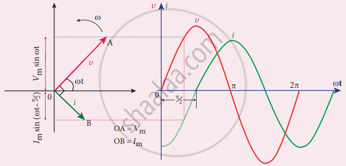
Phasor diagram and wave diagram for AC circuit with L
APPEARS IN
संबंधित प्रश्न
Write the function of a transformer.
Derive an expression for e.m.f. and current in terms of turns ratio
The primary coil of an ideal step-up transformer has 100 turns and the transformation ratio is also 100. The input voltage and power are 220 V and 1100 W, respectively. Calculate the
(a) number of turns in secondary
(b) current in the primary
(c) a voltage across secondary
(d) current in secondary
(e) power in secondary
In a transformer, the frequency of A.C. voltage ______.
Can a transformer be used with direct current source? Give reason.
Describe the construction and working of a transformer with a neat labelled diagram.
A 200V/120V step-down transformer of 90% efficiency is connected to an induction stove of resistance 40 Ω. Find the current drawn by the primary of the transformer.
A step-up transformer has 300 turns of primary winding and 450 turns of secondary winding. A primary is connected to 150 V and the current flowing through it is 9A. The current and voltage in the secondary are
For an ideal step-down transformer, the quantity which is constant for both the coils is ______.
Two coils P and Q are kept near each other. When no current flows through coil P and current increase in coil Q at the rate 10A/s, the emf in coil P is 15mV. When coil Q carries no current and current of 1. 8A flows through coil P, the magnetic flux linked with the coil Q is ______.
