Advertisements
Advertisements
Question
Find out the phase relationship between voltage and current in a pure inductive circuit.
Advertisements
Solution
Consider a circuit containing a pure inductor of inductance L connected across an alternating voltage source. The alternating voltage is given by the equation.
υ = Vm sin ωt …(1)
The alternating current flowing through the inductor induces a self-induced emf or back emf in the circuit. The back emf is given by
Back emf, ε -L `"di"/"dt"`
By applying Kirchoff’s loop rule to the purely inductive circuit, we get

AC circuit with inductor
υ + ε = 0
Vm sin ωt = L`"di"/"dt"`
di = L`"V"_"m"/"L"` sin ωt dt
i = `"V"_"m"/"L" int` sin ωt dt = `"V"_"m"/"L"_omega` (-cos ωt) + constant
The integration constant in the above equation is independent of time. Since the voltage in the circuit has only time dependent part, we can set the time independent part in the current (integration constant) into zero.
`[(cos omega"t" = sin(pi/2 - omega"t")),(- sin (pi/2 - omega"t") = sin (omega"t" - pi/2))]`
i = `"V"_"m"/"L"_omega sin (omega"t" - pi/2) or ` i = `"I"_"m" sin(omega"t" - pi/2)` ....(2)
where `"V"_"m"/"L"_omega = "I"_"m"`, the peak value of the alternating current in the circuit. From equation (1) and (2), it is evident that current lags behind the applied voltage by `pi/2` in an inductive circuit.
This fact is depicted in the phasor diagram. In the wave diagram also, it is seen that current lags the voltage by 90°.
Inductive reactance XL:
The peak value of current Im is given by Im = `"V"_"m"/"L"_omega`. Let us compare this equation with Im = `"V"_"m"/"R"` from resistive circuit. The equantity ωL Plays the same role as the resistance in resistive circuit. This is the resistance offered by the inductor, called inductive reactance (XL). It is measured in ohm.
XL = ωL
The inductive reactance (XL) varies directly as the frequency.
XL = 2πfL …….. (3)
where ƒ is the frequency of the alternating current. For a steady current, ƒ= 0. Therefore, XL = 0. Thus an ideal inductor offers no resistance to steady DC current.
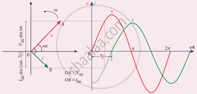
Phasor diagram and wave diagram for AC circuit with L
APPEARS IN
RELATED QUESTIONS
A power transmission line feeds input power at 2200 V to a step-down transformer with its primary windings having 300 turns. Find the number of turns in the secondary to get the power output at 220 V.
The following diagram in Fig. 10.44 shows a coil X connected to a sensitive centre –zero galvanometer G and a coil P connected to a battery through a switch S.
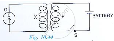
(a) Describe the observation when the switch S is (i) closed suddenly, (ii) then kept closed, (iii) finally opened.
(b) Name and state the law which explains the above observations.
A transformer is designed to work from a 240 V a.c. mains and to give a supply of 8 V to ring a house bell. The primary coil has 4800 turns. How many turns will be in the secondary coil?
Given the input current 15 A and the input voltage of 100 V for a step-up transformer having 90% efficiency, find the output power and the voltage in the secondary if the output current is 3 A.
Give the advantage of AC in long distance power transmission with an illustration.
A transformer is essentially an a.c. device. It cannot work on d.c. It changes alternating voltages or currents. It does not affect the frequency of a.c. It is based on the phenomenon of mutual induction. A transformer essentially consists of two coils of insulated copper wire having different numbers of turns and wound on the same soft iron core.
The number of turns in the primary and secondary coils of an ideal transformer is 2000 and 50 respectively. The primary coil is connected to a main supply of 120 V and secondary coil is connected to a bulb of resistance 0.6 Ω.
The value of current in primary coil is ______.
Define a Transformer.
A transformer is used ______
A step-down transformer connected to an ac mains supply of 220 V is made to operate at 11 V, 44 W lamp. Ignoring power losses in the transformer, what is the current in the primary circuit?
A 60 W load is connected to the secondary of a transformer whose primary draws line voltage. If a current of 0.54 A flows in the load, what is the current in the primary coil? Comment on the type of transformer being used.
