Advertisements
Advertisements
प्रश्न
(i) Explain with the help of a diagram the formation of depletion region and barrier potential in a pn junction.
Advertisements
उत्तर
(i) In a p−n junction, a p-type and an n-type material are joined together. The concentration of holes is higher in p-type material as compared to that in n-type material. Therefore, there is a concentration gradient between the p-type and n-type materials. As a result of this concentration gradient, holes move from p-side to n-side (p → n) by the process of diffusion. Similarly, electrons move from n-side to p-side (n → p).
As the holes diffuse from p-side, they leave ionised spaces (negatively charged) on p-side near the junction. These ionised spaces are immobile. Hence, a negative space-charge region is formed on the p-side near the junction. Similarly, a positive space-charge region is formed on the n-side. These two space-charge regions on either sides of the junction constitute what is called a depletion layer.
Since the n-side loses electrons and p-side gains electrons, a potential difference is developed across the junction of the two regions. This potential difference tends to oppose further motion of electrons from the n-region into the p-region. The same happens for holes too. The reverse polarity of this potential opposes further flow of carriers and is thus called the barrier potential

संबंधित प्रश्न
When a forward bias is applied to a p-n junction, it ______.
In the following diagram, is the junction diode forward biased or reverse biased ?
What is the use of Zener diode?
Draw a labelled diagram of a full wave rectifier. Show how output voltage varies with time if the input voltage is a sinusoidal voltage.
The dynamic plate resistance of a triode value is 10 kΩ. Find the change in the plate current if the plate voltage is changed from 200 V to 220 V.
We use alloys for making standard resistors because they have ____________.
In the depletion region of a diode ______.
- there are no mobile charges.
- equal number of holes and electrons exist, making the region neutral.
- recombination of holes and electrons has taken place.
- immobile charged ions exist.
Consider a box with three terminals on top of it as shown in figure (a):
 (a) |
Three components namely, two germanium diodes and one resistor are connected across these three terminals in some arrangement. A student performs an experiment in which any two of these three terminals are connected in the circuit shown in figure (b).
 (b) |
The student obtains graphs of current-voltage characteristics for unknown combination of components between the two terminals connected in the circuit. The graphs are
(i) when A is positive and B is negative
 (c) |
(ii) when A is negative and B is positive
 (d) |
(iii) When B is negative and C is positive
|
(e) |

(iv) When B is positive and C is negative
 (f) |
(v) When A is positive and C is negative
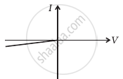 (g) |
(vi) When A is negative and C is positive
 (h) |
From these graphs of current-voltage characteristics shown in figure (c) to (h), determine the arrangement of components between A, B and C.
Which battery connection puts a diode in forward bias?
Which practical effect is associated with forward bias?
