हिंदी

Using the Necessary Circuit Diagrams, Show How the V-i Characteristics of a P-n Junction Are Obtained in Forward Biasing How Are These Characteristics Made Use of in Rectification? - Physics

Advertisements
Advertisements

प्रश्न

Using the necessary circuit diagrams, show how the V-I characteristics of a p-n junction are obtained in

Forward biasing

How are these characteristics made use of in rectification?

Advertisements

उत्तर

 p-n junction diode under forward bias

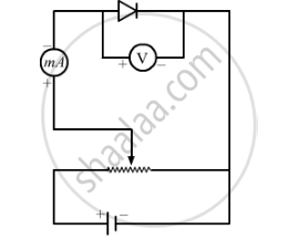
p-side is connected to the positive terminal and n-side to the negative terminal.

Applied voltage drops across the depletion region.

Electron in n-region moves towards the p-n junction and holes in the p-region move towards the junction. The width of the depletion layer decreases and hence, it offers less resistance.

Diffusion of majority carriers takes place across the junction. This leads to the forward current.

The V-I characteristics of p-n junction in forward bias is shown below:

shaalaa.com
  क्या इस प्रश्न या उत्तर में कोई त्रुटि है?
2013-2014 (March) Delhi Set 1

वीडियो ट्यूटोरियलVIEW ALL [3]

संबंधित प्रश्न

With the help of a neat circuit diagram, explain the working of a photodiode. 


Meeta's father was driving her to school. At the traffic signal, she noticed that each traffic light was made of many tiny lights instead of a single bulb. When Meeta asked this question to her father, he explained the reason for this.

Answer the following questions based on above information:

(i) What were the values displayed by Meeta and her father?

(ii) What answer did Meeta's father give?

(iii) What are the tiny lights in traffic signals called and how do these operate?


Carbon, silicon and germanium have four valence electrons each. These are characterised by valence and conduction bands separated by energy band gap respectively equal to (Eg)C, (Eg)Si and (Eg)Ge. Which of the following statements is true?


The width of depletion region of p-n junction diode is _______.

(A) 0.5 nm to 1 nm

(B) 5 nm to 10 nm

(C) 50 nm to 500 nm

(D) 500 nm to 1000 nm


Draw the circuit diagram of an illuminated photodiode in reverse bias. How is photodiode used to measure light intensity?


Explain the formation of depletion layer and potential barrier in a p−n junction.


Explain how a potential barrier is developed in a p-n junction diode.


The wavelength and intensity of light emitted by a LED depend upon ______.


Name the device which converts the change in intensity of illumination to change in electric current flowing through it. Plot I-V characteristics of this device for different intensities. State any two applications of this device.


Why a photo-diode is operated in reverse bias whereas the current in the forward bias is much larger than that in the reverse bias? Explain. Mention its two uses.


Share
Notifications

Englishहिंदीमराठी


      Forgot password?
Use app×