Advertisements
Advertisements
प्रश्न
Draw the circuit diagram of an illuminated photodiode in reverse bias. How is photodiode used to measure light intensity?
Advertisements
उत्तर
The circuit diagram of an illuminated photodiode in reverse bias can be represented as

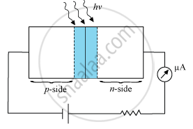
The greater the intensity of light, the greater is the number of photons falling per second per unit area. Thus, the greater the intensity of light, the greater is the number of electron−hole pairs produced at the junction. The photocurrent is, thus, directly proportional to the intensity of light. This can be used for measuring the intensity of incident light.
APPEARS IN
संबंधित प्रश्न
With what considerations in view, a photodiode is fabricated? State its working with the help of a suitable diagram.
Even though the current in the forward bias is known to be more than in the reverse bias, yet the photodiode works in reverse bias. What is the reason?
Sunil and his parents were travelling to their village in their car. On the way his mother noticed some grey coloured panels installed on the roof of a low building. She enquired from Sunil what those panels were and Sunil told his mother that those were solar panels.
(a) What were the values displayed by Sunil and his mother? State one value for each.
(b) In what way would the use of solar panels prove to be very useful?
(c) Name the semiconductor device used in solar panels. Briefly explain with the help of a diagram, how this device works
How is a photodiode fabricated?
Briefly explain its working. Draw its V - I characteristics for two different intensities of illumination ?
Describe briefly, with the help of a diagram, the role of the two important processes involved in the formation of a p-n junction.
Draw solar cell V-I characteristics.
With reference to Semiconductor Physics,
Name the process that causes depletion region in a p-n junction.
The amplifiers X, Y and Z are connected in series. If the voltage gains of X, Y and Z are 10, 20 and 30, respectively and the input signal is 1 mV peak value, then what is the output signal voltage (peak value)
- if dc supply voltage is 10V?
- if dc supply voltage is 5V?
If the resistance R1 is increased (Figure), how will the readings of the ammeter and voltmeter change?

The value of power dissipated across the Zener diode (Vz = 15 V) connected in the circuit as shown in the figure is x × 10–1 watt. The value of x, to the nearest integer, is ______.

