Advertisements
Advertisements
प्रश्न
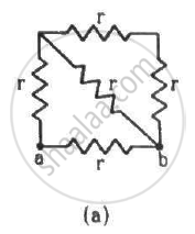
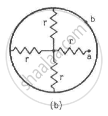
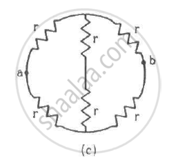
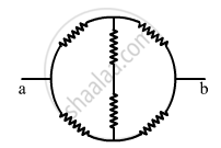
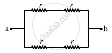
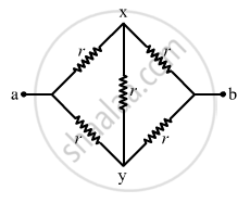
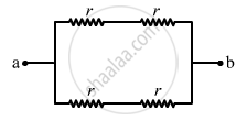
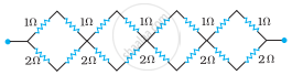
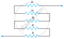
Find the equivalent resistances of the networks shown in the figure between the points a and b.
Advertisements
उत्तर
(a) The circuit can be simplified stepwise, as shown below.
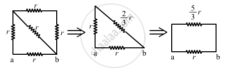
The effective resistance between the points a and b,
\[R_{eff} = \frac{\frac{5r}{3} \times r}{\frac{5r}{3} + r} = \frac{5r}{8}\]
(b) The circuit can be simplified, as shown below.
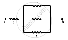
The effective resistance between the points a and b,
\[R_{eff} = \left( \frac{r}{3} \right) + r = \frac{4r}{3}\]
(c)
From the figure, it can be seen that axbya is a balanced Wheatstone bridge. The resistors in branch xy will, thus, become ineffective. The circuit can be simplified as under
The effective resistance between the points a and b,
\[R_{eff} = \left( \frac{2r \times 2r}{2r + 2r} \right) = r\]
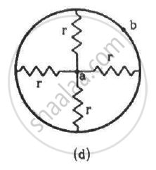
(d) The circuit can be simplified as shown below.
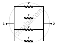
The effective resistance between the points a and b,
\[R_{eff} = \frac{r}{4}\]
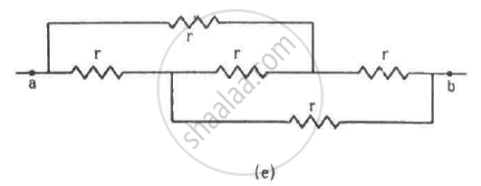
(e) The circuit can be redrawn as shown below.
Now, we can see that the circuit is a balanced Wheatstone bridge. So, the branch xy will become ineffective. Thus, the simplified circuit will become as shown below.
The effective resistance between the points a and b,
\[R_{eff} = \left( \frac{2r \times 2r}{2r + 2r} \right) = r\]
APPEARS IN
संबंधित प्रश्न
Kirchhoff's junction law is equivalent to .............................
(a) conservation of energy.
(b) conservation of charge
(c) conservation of electric potential
(d) conservation of electric flux
State the two Kirchhoff’s rules used in electric networks. How are there rules justified?
Use Kirchhoff's rules to obtain conditions for the balance condition in a Wheatstone bridge.
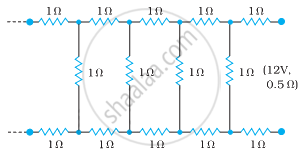
Determine the current drawn from a 12 V supply with internal resistance 0.5 Ω by the infinite network shown in the figure. Each resistor has 1 Ω resistance.
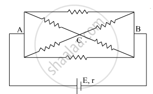
The current is drawn from a cell of emf E and internal resistance r connected to the network of resistors each of resistance r as shown in the figure. Obtain the expression for
- the current draw from the cell and
- the power consumed in the network.
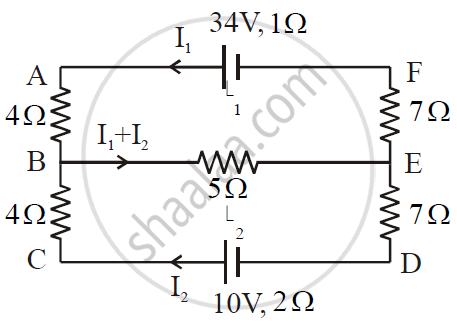
ε1 and ε2 are two batteries having emf of 34V and 10V respectively and internal resistance of 1Ω and 2Ω respectively. They are connected as shown in the figure below. Using Kirchhoff’s Laws of electrical networks, calculate the currents I1 and I2.
Given the resistances of 1 Ω, 2 Ω, 3 Ω, how will be combine them to get an equivalent resistance of (11/5) Ω?
Given the resistances of 1 Ω, 2 Ω, 3 Ω, how will be combine them to get an equivalent resistance of 6 Ω?
Determine the equivalent resistance of networks shown in Fig.
Determine the equivalent resistance of networks shown in Fig.
State Kirchhoff's rules for an electric network. Using Kirchhoff's rules, obtain the balance condition in terms of the resistances of four arms of Wheatstone bridge.
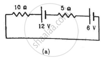
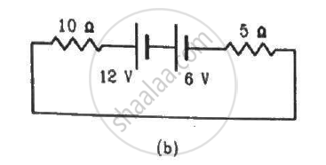
Consider the circuit shown in the figure. Find (a) the current in the circuit (b) the potential drop across the 5 Ω resistor (c) the potential drop across the 10 Ω resistor (d) Answer the parts (a), (b) and (c) with reference to the figure.
A capacitor of capacitance 8.0 μF is connected to a battery of emf 6.0 V through a resistance of 24 Ω. Find the current in the circuit (a) just after the connections are made and (b) one time constant after the connections are made.
State Kirchhoff’s current rule.
State the principle of potentiometer.
State and explain Kirchhoff’s rules.
Explain the determination of unknown resistance using meter bridge.
How the emf of two cells are compared using potentiometer?
Lightning is a very good example of a natural current. In typical lightning, there is 109 J energy transfer across the potential difference of 5 × 10⁷ V during a time interval of 0.2 s. Using this information, estimate the following quantities:
- the total amount of charge transferred between cloud and ground
- the current in the lightning bolt
- the power delivered in 0.2 s.
The instrument for the accurate measurement of the e.m.f of a cell is ______.
Kirchhoff’s second law is a consequence of law of conservation of ______.
Assertion: Kirchhoff’s junction rule follows from conservation of charge.
Reason: Kirchhoff’s loop rule follows from conservation of momentum.
The Kirchhoff's second law (ΣiR = ΣE), where the symbols have their usual meanings, is based on ______.
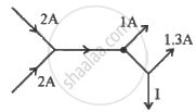
The figure below shows current in a part of electric circuit. The current I is ______.
Kirchhoff s second law is based on the law of conservation of ______
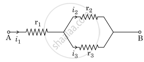
Three resistors having resistances r1, r2 and r3 are connected as shown in the given circuit. The ratio `i_3/i_1` of currents in terms of resistances used in the circuit is:
Three resistors having resistances r1, r2 and r3 are connected as shown in the given circuit. The ratio `"i"_3/"i"_1` of currents in terms of resistances used in the circuit is :
In a meter bridge the point D is a neutral point (Figure).
- The meter bridge can have no other neutral point for this set of resistances.
- When the jockey contacts a point on meter wire left of D, current flows to B from the wire.
- When the jockey contacts a point on the meter wire to the right of D, current flows from B to the wire through galvanometer.
- When R is increased, the neutral point shifts to left.
What are the advantages of the null-point method in a Wheatstone bridge? What additional measurements would be required to calculate `R_(unknown)` by any other method?
What is the advantage of using thick metallic strips to join wires in a potentiometer?
Power P is to be delivered to a device via transmission cables having resistance RC. If V is the voltage across R and I the current through it, find the power wasted and how can it be reduced.
The value of current in the 6Ω resistance is ______.

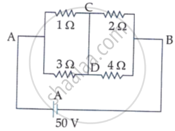
A constant voltage of 50 V is maintained between the points A and B of the circuit shown in the figure. The current through the branch CD of the circuit is: