Advertisements
Advertisements
प्रश्न
An inductor-coil of inductance 17 mH is constructed from a copper wire of length 100 m and cross-sectional area 1 mm2. Calculate the time constant of the circuit if this inductor is joined across an ideal battery. The resistivity of copper = 1.7 × 10⁻⁸ Ω-m.
Advertisements
उत्तर
Given:-
Inductance, L = 17 mH
Length of the wire, l = 100 m
Cross-sectional area of the wire, A = 1 mm2 = 1 × 10⁻⁶ m2
Resistivity of copper, ρ = 1.7 × 10⁻⁸ Ω-m
Now,
\[R = \frac{\rho l}{A}\]
\[ = \frac{1 . 7 \times {10}^{- 8} \times 100}{1 \times {10}^{- 6}} = 1 . 7 \Omega\]
The time constant of the L-R circuit is given by
\[\tau = \frac{L}{R} = \frac{17 \times {10}^{- 3}}{1 . 7}\]
\[= {10}^{- 2} s = 10 ms\]
APPEARS IN
संबंधित प्रश्न
A voltage V = V0 sin ωt is applied to a series LCR circuit. Derive the expression for the average power dissipated over a cycle. Under what condition (i) no power is dissipated even though the current flows through the circuit, (ii) maximum power is dissipated in the circuit?
A source of ac voltage v = v0 sin ωt, is connected across a pure inductor of inductance L. Derive the expressions for the instantaneous current in the circuit. Show that average power dissipated in the circuit is zero.
Derive an expression for the average power consumed in a series LCR circuit connected to a.c. source in which the phase difference between the voltage and the current in the circuit is Φ.
An LR circuit having a time constant of 50 ms is connected with an ideal battery of emf ε. find the time elapsed before (a) the current reaches half its maximum value, (b) the power dissipated in heat reaches half its maximum value and (c) the magnetic field energy stored in the circuit reaches half its maximum value.
A solenoid having inductance 4.0 H and resistance 10 Ω is connected to a 4.0 V battery at t = 0. Find (a) the time constant, (b) the time elapsed before the current reaches 0.63 of its steady-state value, (c) the power delivered by the battery at this instant and (d) the power dissipated in Joule heating at this instant.
An inductor of inductance 2.00 H is joined in series with a resistor of resistance 200 Ω and a battery of emf 2.00 V. At t = 10 ms, find (a) the current in the circuit, (b) the power delivered by the battery, (c) the power dissipated in heating the resistor and (d) the rate at which energy is being stored in magnetic field.
Consider the circuit shown in figure. (a) Find the current through the battery a long time after the switch S is closed. (b) Suppose the switch is again opened at t = 0. What is the time constant of the discharging circuit? (c) Find the current through the inductor after one time constant.

(i) An a.c. source of emf ε = 200 sin omegat is connected to a resistor of 50 Ω . calculate :
(1) Average current (`"I"_("avg")`)
(2) Root mean square (rms) value of emf
(ii) State any two characteristics of resonance in an LCR series circuit.
Using the phasor diagram, derive the expression for the current flowing in an ideal inductor connected to an a.c. source of voltage, v= vo sin ωt. Hence plot graphs showing the variation of (i) applied voltage and (ii) the current as a function of ωt.
A series LCR circuit with L = 0.12 H, C = 480 nF, R = 23 Ω is connected to a 230 V variable frequency supply.
(a) What is the source frequency for which current amplitude is maximum. Obtain this maximum value.
(b) What is the source frequency for which average power absorbed by the circuit is maximum. Obtain the value of this maximum power.
(c) For which frequencies of the source is the power transferred to the circuit half the power at resonant frequency? What is the current amplitude at these frequencies?
(d) What is the Q-factor of the given circuit?
In an L.C.R. series a.c. circuit, the current ______.
Assertion: When the frequency of the AC source in an LCR circuit equals the resonant frequency, the reactance of the circuit is zero, and so there is no current through the inductor or the capacitor.
Reason: The net current in the inductor and capacitor is zero.
A coil of 40 henry inductance is connected in series with a resistance of 8 ohm and the combination is joined to the terminals of a 2 volt battery. The time constant of the circuit is ______.
To reduce the resonant frequency in an LCR series circuit with a generator
In series LCR AC-circuit, the phase angle between current and voltage is
A coil of 0.01 henry inductance and 1 ohm resistance is connected to 200 volt, 50 Hz ac supply. Find the impedance of the circuit and time lag between max. alternating voltage and current.
An alternating voltage of 220 V is applied across a device X. A current of 0.22 A flows in the circuit and it lags behind the applied voltage in phase by π/2 radian. When the same voltage is applied across another device Y, the current in the circuit remains the same and it is in phase with the applied voltage.
- Name the devices X and Y and,
- Calculate the current flowing in the circuit when the same voltage is applied across the series combination of X and Y.
Draw the phasor diagram for a series LRC circuit connected to an AC source.
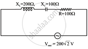
The net impedance of circuit (as shown in figure) will be ______.
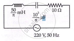
In the given circuit, rms value of current (Irms) through the resistor R is: