- A d.c. A motor works on the principle that a current-carrying conductor placed normally in a magnetic field experiences a force, producing rotational motion.
- The split ring commutator reverses the direction of current in the coil after every half rotation, so that the coil continues to rotate in the same direction.
- The armature coil experiences an anticlockwise couple due to equal and opposite forces on its arms, causing continuous rotation of the coil.
- In a d.c. Motor, electrical energy supplied by the battery is converted into mechanical energy.
Definitions [30]
Define the following term:
Angle of dip
The angle between the horizontal and earth’s magnetic field is known as the angle of dip.
Define the following term regarding a bar magnet:
Magnetic field
The region around a magnet where its magnetic force can be experienced is called the magnetic field.
Define artificial magnet.
Pieces of iron and other magnetic materials which can be made to acquire the properties of natural magnets are called artificial magnets.
Define the following term regarding a bar magnet:
Magnetic axis
An imaginary line (XY) passing through the magnetic north pole and magnetic south pole of a bar magnet is called its magnetic axis.
Define the terms magnet and magnetism.
The substances which have the property of attracting small pieces of iron, nickel, cobalt, etc, are called magnets, and this property of attraction is called magnetism.
Define the following term regarding a bar magnet:
Magnetic equator
An imaginary line (PQ) bisecting the effective length of a magnet is called the magnetic equator of the magnet.
Define natural magnet.
It is a piece of lodestone, which is a black iron oxide (Fe3 O4) called magnetite. The word lodestone means a leading stone.
Define electromagnet.
lt is a solenoid with a soft iron core placed inside it. When current is passed through the solenoid, the soft iron core becomes a temporary magnet.
Define the following term regarding a bar magnet:
Effective length
The distance (NS) between the north pole and south pole of a magnet is called the length or effective length of the magnet.
Definition: Magnetic Field
A magnetic field is the region of space around a magnet or a current-carrying conductor within which a magnetic force can be experienced by another magnet or moving charge.
SI Unit: Tesla (T)
Nature: Vector quantity
Define magnetic shielding.
The process of stopping the magnetic field from entering a region is called magnetic shielding.
Define magnetic flux density.
The number of magnetic field lines crossing unit area kept normal to the direction of field lines is called magnetic flux density. Its unit is Wb/m2
Define magnetic field lines.
The magnetic field lines are the lines drawn in a magnetic field along which a north magnetic pole would move. The magnetic field lines are also known as magnetic lines of force.
Define the Isogonic line.
A line that joins all the places on earth, having the same angle of declination is called an isogonic line.
Define the agonic line.
A line which joins all the places on earth, having zero angle of declination is called agonic line.
Define magnetic field lines of force.
The path in a magnetic field in which a unit north pole tends to move when allowed to do so is known as magnetic field lines of force.
Define the isoclinic line.
A line joining all the places on globe, having same angle of dip or inclination is called isoclinic line.
Define the magnetic effect of electric current.
A current-carrying conductor is always associated with a magnetic field around it is called the magnetic effect of current. It was first discovered by Hans Christian Oersted in 1820.
Definition: Magnetic Effect of Current
The phenomenon in which a current-carrying conductor produces a magnetic field around itself is called the magnetic effect of electric current.
Define electric motor.
lt is a device to convert electrical energy into mechanical energy. It is based on the principle that when a current-carrying coil is placed in a magnetic field, it experiences a force.
Definition: Electric Motor
A device changing electrical energy into mechanical energy is known as electric motor.
Definition: Electromagnetic Induction
The phenomenon in which electric current is generated in a conductor or closed coil due to a varying magnetic field is called electromagnetic induction.
Definition: Faraday's Law of Induction
Whenever the number of magnetic lines of force (magnetic flux) passing through a coil changes, an electric current is induced in the coil. This current is called the induced current.
Define the right-hand thumb rule.
If the current-carrying conductor is held in the right hand such that the thumb points in the direction of the current, then the direction of the curl of the fingers will give the direction of the magnetic field.
Definition: A.C. Generator
An a.c. generator is a device which converts the mechanical energy into the electrical energy using the principle of electromagnetic induction.
Definition: Simple D.C. Motor
An electric motor is a device which converts the electrical energy into the mechanical energy.
Define an electric generator or a dynamo.
lt is a device to convert mechanical energy into electrical energy. It is based on the principle of electromagnetic induction that a current is induced in a closed circuit when the magnetic field passing through it changes.
Definition: Transformer
An electrical device which converts low alternating voltage at high current to high alternating voltage at low current (or vice versa) — i.e., a device which reduces or increases the voltage in an AC circuit through mutual induction — is called a transformer.
Define a Transformer.
The transformer is a device used for converting low voltage into high voltage and high voltage into low voltage. It works on the principle of electromagnetic induction.
Define step up and step down transformer.
Step-up transformer: The transformer used to change a low alternating voltage to a high alternating voltage is called a step-up transformer, (ie) (Vs > Vp).
Step down transformer: The transformer used to change a high alternating voltage to a low alternating voltage is called a step-down transformer (Vs < Vp).
Formulae [4]
Formula: Turns Ratio / Voltage Ratio
\[\frac{V_s}{V_p}=\frac{N_s}{N_p}=k\]
Where:
- Vs = Secondary (output) voltage (V)
- Vp = Primary (input) voltage (V)
- Ns = Number of turns in secondary coil
- Np = Number of turns in primary coil
- k = Transformation ratio (turns ratio)
Formula: Current Ratio (Ideal Transformer)
\[\frac{I_p}{I_s}=\frac{N_s}{N_p}=\frac{V_s}{V_p}\]
Formula: Combined Transformer Equation
\[\frac{V_s}{V_p}=\frac{N_s}{N_p}=\frac{I_p}{I_s}=k\]
Formula: Ideal Transformer
Pinput = Poutput
Theorems and Laws [6]
Write Fleming’s left hand rule.
Stretch the index finger, the middle finger, and the thumb of the left hand mutually perpendicular to each other. If the index finger is in the direction of the magnetic field and the middle finger points in the direction of the current, then the thumb will point towards the direction of the force on the conductor.
State Faraday’s laws of electromagnetic induction.
First law: Whenever there is a change of magnetic flux in a closed circuit, an induced emf is produced in the circuit. This law is a qualitative law as it only indicates the characteristics of induced emf.
Second law: The magnitude of the induced emf produced in the circuit is directly proportional to the rate of change of the magnetic flux linked with the circuit. This law is known as the quantitative law, as it gives the magnitude of the induced emf.
Faraday’s First Law: Whenever the magnetic flux linked with a circuit changes, an emf is induced in the circuit.
Faraday’s Second Law: The magnitude of the induced emf is equal to the rate of change of magnetic flux.
e = `-(d phi)/dt`
For a coil of N turns:
e = `-N (d phi)/dt`
Negative sign indicates Lenz’s law (direction opposes cause).
State Lenz’s Law.
It is stated that the direction of induced e.m.f. is always in such a direction that it opposes the change in magnetic flux.
e = `(d phi)/(dt)`
Consider a rectangular metal coil PQRS. Let ‘L’ be the length of the coil. It is placed in a partly magnetic field ‘B’. The direction of the magnetic field is perpendicular to the paper and into the paper. The ‘x’ part of the coil is in the magnetic field at instant t. If the coil is moved towards the right with a velocity v = `dx/dt` with the help of an external agent, such as a hand. The magnetic flux through the coil is:
Φ = BA = BLx
∴ Φ = BLx ...(1)
There is relative motion of a current through the coil. Let ‘i’ be current through the coil.
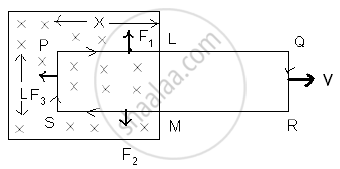
Three forces act on the coil.
F1 on conductor PL ∴ F1 = Bi x, vertically upward.
F2 on conductor MS ∴ F2 = Bi x, vertically downward.
F3 on conductor SP ∴ F3 = Bi L towards left.
F1 and F2 are equal and opposite and also on the same line. They will cancel each other; F3 is a resultant force. The external agent has to do work against this force.
∴ F3 = −Bi l ...(−ve sign indicates that force is opposite to dx.)
If dx is the displacement in time dt, then the work done (dw) = F3 dx.
∴ dw = − BiL dx
This power is an electrical energy ‘ei’ where ‘e’ is an induced e.m.f.
∴ ei = `-(B_i ldx)/(dt)`
∴ e = `-(BLdx)/(dt)`
∴ e = −BLv
∴ e = `-d/dt (BLx)`
∴ e = `(-d phi)/(dt)` ...[from eq (1)]
Lenz’s Law states that the direction of the induced electromotive force (EMF) and the resulting current in a conductor is always such that it opposes the change in magnetic flux that caused it.
Mathematically, Lenz’s Law is expressed as:
ε = `(-d phi_B)/dt`
Where,
ε = Induced EMF
ΦB = Magnetic flux
The negative sign indicates opposition to the change in flux.
Law: Faraday's Second Law or Lenz's Law
Statement:
The direction of the induced emf, or the induced current, in any circuit is such as to oppose the cause that produces it. This law is known as Lenz’s Law.
Explanation / Proof:
- When the north pole of a magnet is moved towards the coil, an induced current flows in the coil in such a direction that the near (left) face of the coil behaves like a north pole.
- Due to the repulsion between the like poles, the motion of the magnet towards the coil is opposed.
- When the north pole of the magnet is moved away from the coil, the induced current flows in such a direction that the near face of the coil becomes a south pole.
- The attraction between opposite poles then opposes the motion of the magnet away from the coil.
In both cases, the induced current opposes the magnet's motion, which is the cause of the current. Therefore, work has to be done to move the magnet, and this mechanical work appears as electrical energy in the coil.
Direction of Induced Current (Fleming’s Right-Hand Rule):
- Stretch the right-hand thumb, forefinger, and middle finger so that they are mutually perpendicular.
- The forefinger points in the direction of the magnetic field.
- The thumb points in the direction of motion of the conductor.
- The middle finger then gives the direction of the induced current.
Conclusion:
Lenz’s Law shows that the induced current always acts in such a direction as to oppose the cause that produces it. This ensures that mechanical energy is converted into electrical energy, and no energy is produced without work being done.
Law: Faraday's First Law or Neumann’s law
Statement:
When the magnetic flux through a circuit is changing, an induced electromotive force (emf) is set up in the circuit whose magnitude is equal to the negative rate of change of magnetic flux. This is also known as Neumann’s Law.
Mathematical Expression:
If ΔΦB is the change in magnetic flux in a time interval Δt, then the induced emf e is given by:
e = \[-\frac{\Delta\Phi_B}{\Delta t}\]
In the limiting case as Δt → 0:
e = \[-\frac{d\Phi_{B}}{dt}\]
- If dΦB is in weber (Wb) and dtdtdt in seconds (s), then the emf eee will be in volts (V).
- This equation represents an independent experimental law, which cannot be derived from other experimental laws.
For a tightly-wound coil of N turns, the induced emf becomes:
e = \[-N\frac{d\Phi_B}{dt}\] or e = \[-\frac{d(N\Phi_B)}{dt}\]
Here, NΦB is called the ‘number of magnetic flux linkages’ in the coil, and its unit is weber-turns.
Explanation:
Consider a magnet and a coil:
- When the north pole of a magnet is near a coil, a certain number of magnetic flux lines pass through the coil.
- If either the coil or the magnet is moved, the number of magnetic flux lines (i.e., the magnetic flux) through the coil changes.
Cases:
- Magnet moved away from the coil → Decrease in magnetic flux through the coil.
- Magnet brought closer to the coil → Increase in magnetic flux through the coil.
In both cases, an emf is induced in the coil during the motion of the magnet.
- Faster motion → Greater rate of change of flux → Higher induced emf.
- If both the magnet and coil are stationary, or both are moving in the same direction with the same velocity, there is no change in flux → No induced emf.
Special Case:
- If the coil is an open circuit (i.e., infinite resistance), emf is still induced, but no current flows.
- This shows that it is the change in magnetic flux that induces emf, not current.
Conclusion:
Neumann’s Law establishes that a changing magnetic flux through a circuit induces an emf, and the induced emf is proportional to the rate of change of flux, with a negative sign indicating the direction (as per Lenz’s law).
Law: Principle of a Transformer
A transformer is based on the principle of mutual induction, i.e., whenever the magnetic flux linked with a coil changes, an emf is induced in the neighbouring coil. For an ideal transformer there is no loss of power, so Pinput = Poutput. On the basis of winding, transformers are of two types — step-up and step-down.
Key Points
Key Points: Magnetic Field
- A magnetic field is the region around a magnet or current-carrying conductor where its effect can be detected (shown by the pin/iron-filing activity).
- Oersted (1820) showed that current produces a magnetic effect.
- Faraday introduced the term "magnetic lines of force."
- The magnetic field is a vector quantity; the compass-needle convention gives its direction.
- Significance: electric motors, generators, Earth's magnetism, and electromagnetism as a fundamental force.
Key Points:
- A current-carrying conductor in a magnetic field experiences a force perpendicular to both the current and the field direction.
- Reversing current or reversing field polarity reverses the force direction.
- Formula: F = BIl sin θ; vector form \[\vec F\] = I\[\vec l\] × \[\vec B\].
- Force is zero when the wire is parallel to \[\vec{B}\] and maximum (Fmax = BIl) when perpendicular.
- Fleming's Left-Hand Rule (thumb = force, forefinger = field, middle finger = current) is the standard tool for direction in Indian board exams.
Key Points: Introduction to Electromagnetic Induction
- Electricity and magnetism are interrelated.
- Electric current can produce a magnetic field.
- A changing magnetic field can produce electric current.
- The production of electric current by a varying magnetic field is called electromagnetic induction.
- Michael Faraday showed in 1831 that a moving magnet can produce current in a conductor.
- The current produced due to electromagnetic induction is called induced current.
- Generators, transformers, induction motors, and wireless chargers work on electromagnetic induction.
Key Points: Simple D.C. Motor
Key Points: Electric Generator
- Electromagnetic induction can be used to generate a large current by rotating a coil in a magnetic field, converting mechanical energy into electrical energy.
- In an AC generator, a coil rotates between magnetic poles, and the induced current reverses direction every half-rotation, producing alternating current (AC).
- Carbon brushes and conducting rings connect the rotating coil to the external circuit; the current direction in the circuit reverses after each half-turn.
- Using a multi-turn coil significantly increases the magnitude of the generated current.
- A DC generator uses a split ring instead of two separate rings to maintain unidirectional current in the external circuit.
Concepts [17]
- Magnet
- Classification of Magnets
- Concept of Magnetic Field
- Properties of magnetic lines of force
- Magnetic Effect of Electric Current
- Force on a Current-Carrying Conductor Placed in a Uniform Magnetic Field
- Force on Parallel Current Carrying Conductors
- Electric Motor
- Introduction to Electromagnetic Induction
- Faraday's Laws of Electromagnetic Induction
- Alternating-Current Generator
- Simple D.C. Motor
- Comparison Between A.C. Generator and D.C. Motor
- Electric Generator
- Transformers
- Types of Transformer
- Uses of Electromagnet
