Advertisements
Advertisements
Question
Figure shows a simple form of an A.C. generator.
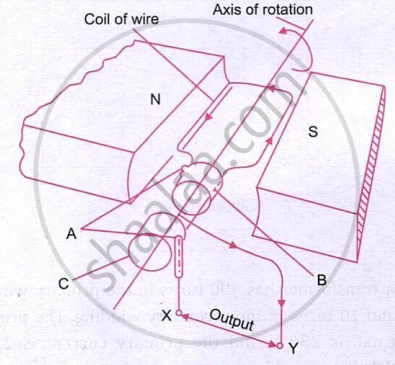
- Name the parts labelled \(A\) and \(B\).
- What would be the effect of doubling the number of turns on the coil if the speed of rotation remains unchanged?
- Which of the output terminals is positive if the coil is rotating in the direction shown in the diagram (anticlockwise)?
- What is the position of the rotating coil when p.d. across its ends is zero? Explain why the p.d. is zero when the coil is at this position.
- Sketch a graph showing how the p.d. across the ends of the rotating coil varies with time for an A.C. dynamo.
- On the same sheet of paper and vertically below the first graph using the same time scale, sketch graphs to show the effect of
- doubling the speed of rotation and at the same time keeping the field and the number of turns constant, and
- doubling the number of turns on the coil and at the same time doubling the speed of rotation of the coil, keeping the speed constant.
Advertisements
Solution
(a) The labels are not visible in the supplied figure. The usual labelled parts of an A.C. generator are the slip rings and carbon brushes; the coil ends connect to the slip rings, which contact the brushes.
(b) Doubling the number of turns doubles the induced e.m.f., while the frequency remains unchanged.
(c) Use Fleming’s right-hand rule to determine the positive terminal from the direction of the induced current. The diagram must be interpreted carefully.
(f) The induced p.d. is zero when the plane of the coil is perpendicular to the magnetic field.
(e) The output is a sinusoidal alternating voltage: \[V=V_{0}\sin(2\pi f t).\]
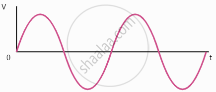
(f) (i)
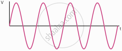
Doubling the rotation speed doubles both the frequency and peak voltage.
(ii)
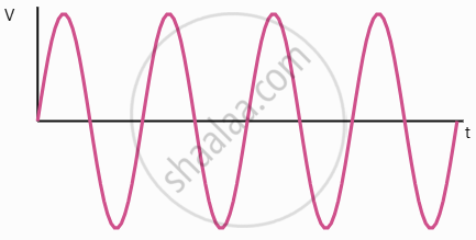
Doubling both the number of turns and rotation speed makes the peak voltage four times and the frequency twice their original values.
