Advertisements
Advertisements
प्रश्न
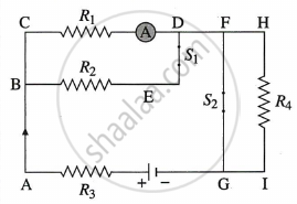
Resistances R1, R2, R3 and R4 are connected as shown in the figure. S1 and S2 are two keys. Discuss the current flowing in the circuit in the following cases.
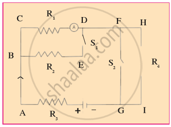
- Both S1 and S2 are closed.
- Both S1 and S2 are open.
- S1 is closed but S2 is open.
Advertisements
उत्तर
a.
Due to the zero resistance of FG in a parallel series combination of R4, the resultant resistance of this combination will also be almost zero, and the entire electric current will flow through the path.
Resultant resistance of parallel series combination of R1, R2
∴ `I_3 = V/(R_3 + R_S)`
`V_1 = V - I_3 R_3`
= `V - (R_3 V)/(R_3 + R_p)`
= `V (1 - R_3/(R_3 + R_p))`
= `V (R_p/(R_3 + R_p))`
∴ `I_1 = V_1/R_1 = V/R_1(R_p/(R_3 + R_p))`
similarly,
`I_2 = V/R_2(R_p/(R_3 + R_p))`
b.
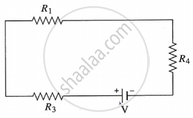
Equivalent resistance of series combination of R1, R3, R4
`R_S = R_1 + R_3 + R_4`
Current in the circuit,
`I = V/(R_1 + R_3 + R_4)`
c.
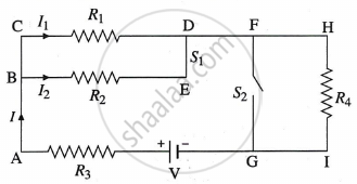
`R_P = (R_1 R_2)/(R_1 + R_2)`
`R_S = R_3 + R_4 + (R_1 R_2)/(R_1 + R_2)`
`I = V/R_S = I_3 = I_4`
Also, `I = I_1 + I_2` and `R_1 I_1 = R_2 I_2`
∴ `I = I_1 + (I_1 R_1)/R_2`
∴ `I_1(1 + R_1/R_2)`
= `(I_1(R_1 + R_2))/R_2`
`I_1 = (R_2 I)/(R_1 + R_2)`
and `I_2 = (I_1 R_1)/R_2`
= `R_1/R_2((R_1 I)/(R_1 + R_2))`
= `(R_1 I)/(R_1 + R_2)`
APPEARS IN
संबंधित प्रश्न
Draw circuit symbols for
fixed resistance
Draw circuit symbols for variable resistance
What is a circuit diagram
How does the short circuit form? What is its effect?
Explain the following:
Open circuit
Right or wrong sentence.
Increasing the current passing through the wire decreases the magnetic field intensity.
______ is the device used to close or open an electric circuit.
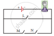
In the circuit shown, which switches (L,M or N) must be closed to light up the bulb?
Draw the circuit diagram for the following series connection
State whether true or false. If false, correct the statement.
Ammeter is connected in parallel in any electric circuit.
Explain about domestic electric circuits. (circuit diagram not required)
What are the types of electric circuits?
In an electrical circuit three incandescent bulbs A, B and C of rating 40 W, 60 W and 100 W respectively are connected in parallel to an electric source. Which of the following is likely to happen regarding their brightness?
A child has drawn the electric circuit to study Ohm’s law as shown in Figure. His teacher told that the circuit diagram needs correction. Study the circuit diagram and redraw it after making all corrections.

Choose the statement which is not correct in the case of an electric fuse.
Our body is a ______ of electricity.
Write a short note on the different electrical circuits.
How is Joule's law effect useful in electric circuits where fuse is used as a safety device?
