Advertisements
Advertisements
प्रश्न
The separation between the plates of a charged parallel-plate capacitor is increased. Which of the following quantities will change?
(a) Charge on the capacitor
(b) Potential difference across the capacitor
(c) Energy of the capacitor
(d) Energy density between the plates
Advertisements
उत्तर
(b) Potential difference across the capacitor
(c) Energy of the capacitor.
Because the charge always remains conserved in an isolated system, it will remain the same.
Now ,
`V = (Qd)/(∈_0A)`
Here, Q, A and d are the charge, area and distance between the plates, respectively.
Thus, as d increases, V increases.
Energy is given by `E = (qV)/2`
So , it will also increase .
Energy density u , that is , energy stored per unit volume in the electric field is given by `u = 1/2∈_0E^2`
So , u will remain constant with increase in distance between the plates .
APPEARS IN
संबंधित प्रश्न
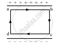
The electric field inside a parallel plate capacitor is E. Find the amount of work done in moving a charge q over a closed loop a b c d a.
Three capacitors each of capacitance 9 pF are connected in series.
- What is the total capacitance of the combination?
- What is the potential difference across each capacitor if the combination is connected to a 120 V supply?
A cylindrical capacitor has two co-axial cylinders of length 15 cm and radii 1.5 cm and 1.4 cm. The outer cylinder is earthed and the inner cylinder is given a charge of 3.5 µC. Determine the capacitance of the system and the potential of the inner cylinder. Neglect end effects (i.e., bending of field lines at the ends).
Suppose a charge +Q1 is given to the positive plate and a charge −Q2 to the negative plate of a capacitor. What is the "charge on the capacitor"?
The plates of a parallel-plate capacitor are given equal positive charges. What will be the potential difference between the plates? What will be the charges on the facing surfaces and on the outer surfaces?
A parallel-plate capacitor having plate area 25 cm2 and separation 1⋅00 mm is connected to a battery of 6⋅0 V. Calculate the charge flown through the battery. How much work has been done by the battery during the process?
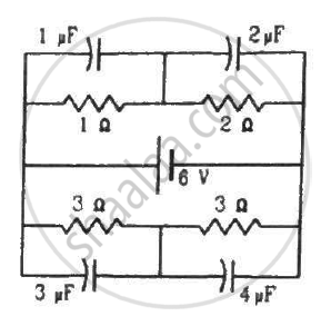
Find the charges on the four capacitors of capacitances 1 μF, 2 μF, 3 μF and 4 μF shown in the figure.
An ac circuit consists of a series combination of circuit elements X and Y. The current is ahead of the voltage in phase by `pi /4` . If element X is a pure resistor of 100Ω ,
(a) name the circuit element Y.
(b) calculate the rms value of current, if rms value of voltage is 141V.
(c) what will happen if the ac source is replaced by a dc source ?
Three different capacitors are·connected in series. Then:-
Capacitors connected in series have ______
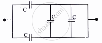
The equivalent capacitance of the combination shown in the figure is ______.
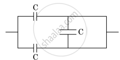
In the following circuit, the equivalent capacitance between terminal A and terminal B is:
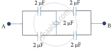
The equivalent capacitance of the combination shown is:
The potential difference that must be applied across the series and parallel combination of 4 identical capacitors such that the energy stored in them becomes the same. The ratio of potential difference in series to parallel combination is ______.
What is the process of replacing a group of capacitors with a single equivalent capacitor that produces the same electrical effect called?
Which formula gives the equivalent capacitance of capacitors in series?
What is the voltage relationship for capacitors in parallel?
Which expressions give the energy stored in series and parallel combinations, respectively?
