Definitions [18]
The work done per unit charge to move a charge between two points in a circuit; it is the driving force for current flow.
An intrinsic property of a material that determines its resistance per unit length and cross-sectional area.
The opposition offered by a conductor to the flow of electric current.
The rate of flow of electric charge through a cross-section of a conductor.
The condition of the Wheatstone bridge under which the galvanometer shows zero (null) deflection, i.e., Ig = 0, is called the balance condition of the bridge.
An arrangement of four resistors used to measure the resistance of one of them in terms of the other three, invented by Samuel Hunter Christie in 1833 and made famous by Sir Charles Wheatstone, is called a Wheatstone bridge.
An electromechanical, sensitive instrument which is used to detect and measure small electric currents in a circuit is called a galvanometer.
The current required to produce a unit deflection (1 division) on the scale.
A Moving Coil Galvanometer (MCG) is a sensitive electromagnetic instrument used to detect and measure small electric currents (of the order of microamperes to milliamperes) by measuring the deflection of a current-carrying coil placed in a uniform magnetic field.
Deflection produced per unit current.
Deflection produced per unit voltage.
Define the term ‘current sensitivity’ of a moving coil galvanometer.
The current sensitivity of a galvanometer is defined as the deflection produced in the galvanometer when a unit current flows through it.
Mathematically, it can be given by:
IS = `(NBA)/k`
Where k is the couple per unit twist.
Current sensitivity is defined as the deflection e per unit current.
Any closed conducting path in an electric network is called a loop or mesh.
Any point in an electric circuit where two or more conductors are joined together is a junction.
A voltmeter is an instrument used to measure the potential difference between two points in an electric circuit.
A galvanometer is a sensitive instrument used to detect and measure small electric currents in a circuit.
An ideal voltmeter is one which has infinite resistance and does not draw any current from the circuit.
A branch is any part of the network that lies between two junctions.
Formulae [10]
Balance condition (when Ig = 0):
- AC → battery arm
- BD → galvanometer arm
- R4 → unknown resistance measured in terms of the other three.
\[R_A=\frac{S\cdot G}{S+G}=\frac{G}{n}\]
S = \[\frac{G\cdot I_g}{I-I_g}\]
If current I = nIg: S = \[\frac {G}{n-1}\]
VS = \[\frac{\phi}{V}=\frac{NAB}{CG}\]
where G = resistance of the galvanometer coil.
Unit: div/V
CS = \[\frac{\phi}{I}=\frac{NAB}{C}\]
Unit: div/A or div/μA
k = \[\frac{I}{\phi}=\frac{C}{NAB}\]
k is the reciprocal of current sensitivity. A galvanometer with a smaller figure of merit is more sensitive.
R = ρ\[\frac {l}{A}\]
where:
- ρ = resistivity (specific resistance)
- l = length of wire
- A = cross-sectional area
\[\frac {X}{R}\] = \[\frac {l_1}{l_2}\]
or
X = \[R\frac{l_1}{100-l_1}\]
where:
- X = unknown resistance
- R = known resistance (from resistance box)
- l₁ = length of wire from one end to the balance point
- l₂ = remaining length of wire
- Total length = 100 cm
r = R\[\left(\frac{l_1}{l_2}-1\right)\]
\[\frac {E_1}{E_2}\] = \[\frac {l_1}{l_2}\]
EMF Ratio (Sum & Difference Method):
\[\frac{E_1}{E_2}=\frac{l_1+l_2}{l_1-l_2}\]
Theorems and Laws [10]
At any junction, the sum of currents entering = the sum of currents leaving.
Example: I1 + I3 = I2 + I4. Based on conservation of charge.
Statement
In any closed loop of an electric circuit, the algebraic sum of all changes in potential is zero.
Derivation
Consider a charge moving around a closed loop. After completing one full loop, the charge returns to its starting point. Since electric potential depends only on position, the net change in potential over a complete loop must be zero.
Therefore, in a closed loop,
If a loop contains cells and resistors, then the total emf supplied by the sources is equal to the total potential drop across the resistors. Thus,
Conclusion
Kirchhoff's Second Law is a direct consequence of the conservation of energy.
Statement
At any junction in an electric circuit, the sum of currents entering the junction is equal to the sum of currents leaving the junction.
Derivation
When the current in a circuit is steady, charge does not accumulate at any junction. Therefore, the amount of charge entering the junction per second must be equal to the amount of charge leaving the junction per second.
If currents I1 and I2 enter a junction and currents I3 and I4 leave it, then
or
Hence,
Conclusion
Kirchhoff's First Law is a direct consequence of the conservation of charge.
The algebraic sum of potential differences in a closed loop is zero.
Based on conservation of energy.
Obtain the balancing condition for the Wheatstone bridge arrangements as shown in Figure 4 below:
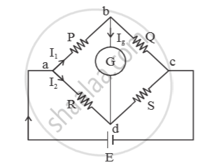
Let `I_3` and `I_4` be the currents in resistors Q and S respectively . Let `I_g` be the current through galvanometer. For balanced condition,
`I_g = 0`
Applying junction law at ‘b’ we get
`I_1 = I_3 + I_g`
`because I_g = 0 , I_1 = I_3` ....(i)
Applying junction law at ‘d’, we get
`I_2 + I_g = I_4`
`because I_g = 0 , I_2 = I_4` ....(ii)
Applying loop law in the loop abda, we get
`-I_1·P - I_g·Q + -I_2·R = 0`
⇒ `-I_1P + I_2R = 0` (`because I_g = 0`)
⇒ `I_1P = I_2R`
⇒ `P/R = I_2/I_1` ....(iii)
Applying loop law in the loop bcdb, we get
`-I_3·Q + I_4·S + I_g·6 = 0`
⇒ `-I_3·Q + I_4·S + 0 = 0 (because I_g =0)`
⇒ `-I_3Q = I_4S`
⇒ `Q/S = I_4/I_3`
⇒ `Q/S = I_2/I_1` ...(iv) [using eq.(i) and (ii)]
From eq. (iii) and (iv), `P/ R = Q/s`
⇒ `P/Q = R/S`
This is the balanced condition.
Step 1: Torque due to current (Deflecting Couple):
- When current I flows through a coil of N turns, area A, in a field B: τdeflecting = N I A B (Since radial field: sin90° = 1)
Step 2: Restoring Torque (Spring):
- The phosphor-bronze strip/spring opposes the deflection. If ϕ is the angular deflection and C (or k) is the torsional constant of the spring, τrestoring = Cϕ
Step 3: Equilibrium Condition:
- At equilibrium, deflecting torque = restoring torque: NIAB = Cϕ
Step 4: Current–Deflection Relationship:
- ϕ = (\[\frac {NAB}{C}\])I
- ϕ ∝ I
The deflection is directly proportional to the current. This makes the scale linear and uniform.
Statement
The potential difference between two points of a uniform wire carrying a constant current is directly proportional to the length of the wire between those points.
V ∝ l or V = Kl
where K is the potential gradient.
Explanation / Proof
When a steady current flows through a uniform wire,
V = IR
Since the resistance of the wire,
R ∝ l
Therefore,
V ∝ l
Thus, potential difference is directly proportional to the length of the wire.
Conclusion
Hence, proved that in a potentiometer, the potential difference varies directly with length, provided the current and temperature remain constant.
Statement
The algebraic sum of all potential differences (voltage drops) and electromotive forces (emfs) in any closed loop of an electrical circuit is zero.
∑I R + ∑ ε = 0
This means that the total voltage supplied in a closed loop is equal to the total voltage drop in that loop.
Sign Convention
- Across a Resistor:
If the loop is traced in the direction of current, the potential drop (IR) is taken as negative.
If the loop is traced against the direction of current, the potential drop (IR) is taken as positive. - Across a Source (emf):
Moving from negative to positive terminal inside the source → emf is taken as positive.
Moving from positive to negative terminal inside the source → emf is taken as negative.
Statement
The algebraic sum of currents at any junction in an electrical network is zero.
∑I = 0
This means that the total current entering a junction equals the total current leaving it.
Sign Convention
- Currents entering the junction are taken as positive.
- Currents leaving the junction are taken as negative.
Thus,
I1 + I3 + I4 − I2 − I5 − I6 = 0
or
I1 + I3 + I4 = I2 + I5 + I6
Statement
A Wheatstone bridge is said to be balanced when no current flows through the galvanometer.
Under this condition, the ratio of resistances in one pair of opposite arms is equal to the ratio in the other pair.
\[\frac {P}{Q}\] = \[\frac {S}{R}\]
Proof / Explanation
Consider four resistances P, Q, R, S forming a bridge.
When the bridge is balanced:
Ig = 0
(No current flows through the galvanometer.)
Applying Kirchhoff’s Voltage Law to the loops:
From loop 1:
I1P = I2S
From loop 2:
I1Q = I2R
Dividing the two equations:
\[\frac {P}{Q}\] = \[\frac {S}{R}\]
Conclusion
When the bridge is balanced:
- No current flows through the galvanometer.
- The above ratio condition holds.
- If any three resistances are known, the fourth can be determined.
Key Points
- Kirchhoff's laws are used for complex circuits.
- Kirchhoff's First Law: Total current entering a junction = total current leaving a junction.
- Kirchhoff's Second Law: Total potential rise in a closed loop = total potential drop in the loop.
- KCL is based on conservation of charge.
- KVL is based on conservation of energy.
- Mathematical forms are ∑I = 0 and ∑V = 0.
- The correct sign convention is essential in numericals.
- Choose some direction of the currents.
- Reduce the number of variables using Kirchhoff's first law.
- Determine the number of independent loops.
- Apply voltage law to all the independent loops.
- Solve the equations obtained simultaneously.
- In case, the answer of a current variable is negative, the conventional current is flowing in the direction opposite to that chosen by us.
- The Wheatstone bridge is used for measuring the values of very low resistance precisely.
- We can also measure quantities such as galvanometer resistance, capacitance, inductance and impedance using a Wheatstone bridge.
- A potentiometer can be used as a voltage divider, where the output voltage is proportional to the length of the wire segment:
V ∝ l - It is used in audio control systems (sliders and rotary knobs) for loudness control and frequency adjustment.
- A potentiometer can work as a motion/displacement sensor, where change in position produces proportional change in potential difference.
- It is more sensitive and more accurate than a voltmeter, capable of measuring very small potential differences (of the order of 10−6 V).
- A potentiometer can measure both emf and potential difference, whereas a voltmeter measures only terminal potential difference.
- Limitations: It is not portable and does not provide direct reading; balancing (null point) is required for measurement.
- A moving-coil galvanometer (MCG) can be converted into an ammeter by connecting a low-resistance shunt (S) in parallel with the galvanometer to increase its current range.
- An ideal ammeter should have zero resistance; the shunt decreases the effective resistance and protects the galvanometer from excess current.
- If G is the galvanometer resistance, Ig is the full-scale deflection current, and I is the total current, then shunt resistance:
S = \[\frac {GI_g}{I-I_{g}}\] - To increase the range nnn times (I = nIg):
S = \[\frac {G}{n-1}\]
- A moving-coil galvanometer (MCG) can be converted into a voltmeter by connecting a high resistance (X) in series to increase its voltage range.
- An ideal voltmeter should have very high (ideally infinite) resistance and always be connected in parallel across the component.
- If G is the galvanometer resistance and Ig is full-scale deflection current, then the required series resistance:
X = \[\frac {V}{I_g}\] - G - If the voltage range is increased nnn times, then:
X = G(n − 1)
Important Questions [19]
- Kirchhoff'S Voltage Law and Current Law Are Respectively in Accordance with the Conservation of
- Obtain the condition for bridge balance in Wheatstone’s bridge.
- What is is Equivalent to Kirchhoff'S Junction Law
- Four Resistances 4ω,8ω,Xω, and 6ω Are Connected in a Series So as to Form Wheatstone’S Network. If the Network is Balanced, Find the Value of ‘X
- State any two sources of errors in the meter-bridge experiment. Explain how they can be minimized.
- Explain with a neat circuit diagram. How you will determine the unknown resistances using a meter bridge.
- Explain How Moving Coil Galvanometer is Converted into a Voltmeter. Derive the Necessary Formula.
- A Rectangular Coil of a Moving Coil Galvanometer Contains 100 Turns, Each Having Area 15 cm^2. It is Suspended in the Radial Magnetic Field 0.03 T.
- The Fraction of the Total Current Passing Through the Galvanometer is ............ .
- A Moving Coil Galvanometer Has a Resistance of 25ω and Gives a Full Scale Deflection for a Current of 10ma. How Will You Convert It into a Voltmeter Having Range 0 - 100 V?
- A Galvanometer Has a Resistance of 16ω. It Shows Full Scale Deflection, When a Current of 20 Ma is Passed Through It. the Only Shunt Resistance Available is 0.06 Which is Not Ap
- State how a moving coil galvanometer can be converted into an ammeter.
- The Combined Resistance of a Galvanometer of Resistance 500Ω and Its Shunt is 21Ω. Calculate the Value of Shunt
- To convert a moving coil galvanometer into an ammeter we need to connect a ______.
- Calculate the Sensitivity of the Moving Coil Galvanometer
- Show that the Current Flowing Through a Moving Coil Galvanometer is Directly Proportional to the Angle of Deflection of Coil.
- Obtain the Expression for Current Sensitivity of Moving Coil Galvanometer.
- A Circular Coil of 250 Turns and Diameter 18 Cm Carries a Current Of 12a. What is the Magnitude of Magnetic Moment Associated With the Coil?
- An Ideal Voltmeter Has ?
