Advertisements
Advertisements
प्रश्न
Three resistors are connected to a 6 V battery as shown in the figure given below:
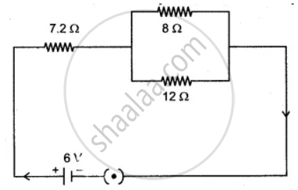
Calculate:
(i) the equivalent resistance of the circuit.
(ii) total current in the circuit.
(iii) potential difference across the 7.2 Ω resistor.
Advertisements
उत्तर
(i) `1/"R"_1 = 1/8 + 1/12`
`= (3 + 2)/24 = 5/24`
R1 = 4.8 ohm.
Total Resistance = 4.8 + 7.2 = 12 ohm
(ii) V = IR
6 = I × 12
I = 0.5 Amp.
(iii) V = IR
= 0.5 × 7.2
= 3.6 Volt.
संबंधित प्रश्न
Define one coulomb charge.
State whether a voltmeter has a high resistance of a low resistance. Give reason for your answer.
The p.d. across a lamp is 12 V. How many joules of electrical energy are changed into heat and light when: a current of 2 A flows through it for 10 s?
What current will be taken by a 920 W appliance if the supply voltage is 230 V?
Three electric cells of potential difference 1.5 V each have been connected as a battery. The potential differences of the battery will be ____________ V.
A current of 0.2 A flows through a wire whose ends are at a potential difference of 15 V. Calculate:
(i) The resistance of the wire, and
(ii) The heat energy produced in 1 minute.
Explain why potential difference is always less than the e.m.f. of a cell?
A cell of e.m.f 2.0 V and internal resistance 1Ω is connected to the resistors of 3Ω and 6Ω in series. Calculate:
(i) the current drawn from the cell,
(ii) the p.d. across each resistor,
(iii) the terminal voltage of the cell and
(iv) the voltage drop.
Twenty-seven drops of same size are charged at 220 V each. They combine to form a bigger drop. Calculate the potential of the bigger drop.
Study the following circuit and find:

- Effective resistance of the circuit
- Current drawn from the battery
- Potential difference across the 5 omega resistor
