Advertisements
Advertisements
प्रश्न
Draw a labelled diagram of a moving coil galvanometer. Describe briefly its principle and working.
Advertisements
उत्तर
Principle:
Its working is based on the fact that when a current carrying coil is placed in a magnetic field, it experiences a torque.
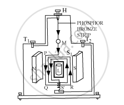
Working:
Suppose the coil PQRS is suspended freely in the magnetic field.
Let l = length PQ or RS of the coil
b = breadth QR or SP of the coil
n = number of turns in the coil
Area of each turn of the coil, A = l × b
Let B = strength of the magnetic field in which the coil is suspended
I = current passing through the coil in the direction PQRS
At any instant, let α be the angle that the normal drawn on the plane of the coil makes with the direction of magnetic field.
The rectangular coil carrying current, when placed in the magnetic field, experiences a torque whose magnitude is given by:
τ = nIBA sinα
Due to the deflecting torque, the coil rotates and the suspension wire gets twisted. A restoring torque is set up in the suspension wire.
Let θ be the twist produced in the phosphor bronze strip due to the rotation of the coil and K be the restoring torque per unit twist of the phosphor bronze strip. Then, we have:
Total restoring torque produced = kθ
In equilibrium position of the coil, we have:
Deflecting torque = Restoring torque
∴ NIBA = kθ
or
`I=k/(NBA)theta " or "Gtheta`
Here,
`K/(NBA)=G=a["constant for a galvanometer"]`
It is known as galvanometer constant.
APPEARS IN
संबंधित प्रश्न
Two moving coil meters, M1 and M2 have the following particulars:
R1 = 10 Ω, N1 = 30,
A1 = 3.6 × 10⁻³ m2, B1 = 0.25 T
R2 = 14 Ω, N2 = 42,
A2 = 1.8 × 10⁻³ m2, B2 = 0.50 T
(The spring constants are identical for the two meters.)
Determine the ratio of
- current sensitivity and
- voltage sensitivity of M2 and M1.
A rectangular coil of a moving coil galvanometer contains 100 turns, each having area
15 cm2. It is suspended in the radial magnetic field 0.03 T. The twist constant of suspension
fibre is 15 x 10-10 N-m/degree. Calculate the sensitivity of the moving coil galvanometer.
A galvanometer has a resistance of 16Ω. It shows full scale deflection, when a current of 20 mA is passed through it. The only shunt resistance available is 0.06 which is not appropriate to convert a galvanometer into an ammeter. How much resistance should be connected in series with the coil of galvanometer, so that the range of ammeter is 8 A?
With the help of a neat and labelled diagram, explain the principle and working of a moving coil galvanometer ?
Define current sensitivity of a galvanometer.
The AC voltage across a resistance can be measured using a ______.
In a moving coil galvanometer the deflection (Φ) on the scale by a pointer attached to the spring is ______.
A moving coil galvanometer can be converted into an ammeter by ______.
Current sensitivity of a galvanometer is defined as the:
A voltmeter is connected across a component:
