Definitions [31]
The phenomenon in which electric current is generated in a conductor or closed coil due to a varying magnetic field is called electromagnetic induction.
Magnetic flux linked with any surface is equal to the total number of magnetic lines of force passing normally through it.
Magnetic flux (ΦB) is the measure of magnetic field lines passing through a surface.
Define the right-hand thumb rule.
If the current-carrying conductor is held in the right hand such that the thumb points in the direction of the current, then the direction of the curl of the fingers will give the direction of the magnetic field.
Whenever the number of magnetic lines of force (magnetic flux) passing through a coil changes, an electric current is induced in the coil. This current is called the induced current.
The direction of the induced EMF (and hence the induced current) in a closed conducting loop is always such that it opposes the change in magnetic flux that produced it.
The emf induced across the ends of a conductor due to its motion in a magnetic field is called motional emf.
Eddy currents are circulating currents induced in the bulk of a conductor when the magnetic flux linked with it changes.
They are named after the whirlpool-like eddies formed in flowing water.
For a closely wound coil of N turns, the total magnetic flux associated with the coil is called the flux linkage.
Inductance is the ratio of total magnetic flux linkage to the current producing it.
Define mutual inductance.
The mutual inductance (M) of two circuits (or coils) is the magnetic flux (Φs) linked with the secondary circuit per unit current (IP) of the primary circuit.
The property of two coils by which a change in current in one coil induces an emf in the other coil — equal to the magnetic flux linked with one circuit per unit current in the other, or the value of induced emf produced in the secondary circuit per unit rate of change in current in the primary circuit — is called mutual inductance.
OR
Mutual Inductance (M) of a pair of coils is defined as the ratio of the total magnetic flux linkage in the secondary coil to the current in the primary coil that produces it.
The coefficient of coupling K between two coils is the fraction of the total magnetic flux produced by one coil that links with the other coil.
The property of a coil by which it opposes the change in its own current and induces an emf in itself — numerically equal to the ratio of magnetic flux (produced due to current in the circuit) linked with the circuit to the current flowing in it, or the ratio of induced emf produced around the circuit to the rate of change of current in it — is called self-inductance.
OR
The self-inductance (L) of a coil is defined as the ratio of the total magnetic flux linkage through the coil to the current flowing in it. Equivalently, it equals the magnitude of the induced EMF per unit rate of change of current.
Define the coefficient of self-induction.
It is defined as magnetic flux linked with the solenoid when unit current flows through it.
Define self-inductance.
The self-inductance of a circuit is the ratio of magnetic flux (produced due to current in the circuit) linked with the circuit to the current flowing in it.
An a.c. generator is a device which converts the mechanical energy into the electrical energy using the principle of electromagnetic induction.
The voltage that varies sinusoidally with time, expressed as v = vm sin ωt, is called alternating voltage.
The square root of the mean of the squares of the instantaneous current values over one complete cycle, equal to im\[\sqrt{2}\], is called the root mean square current (or effective current).
The current whose magnitude changes with time and direction reverses periodically is called alternating current (AC).
A phasor is a rotating vector about the origin with a constant angular speed ω\omegaω. Its vertical component at any instant gives the instantaneous sinusoidally varying value of the AC quantity (voltage v or current i) it represents.
The effective resistance offered by an inductor to the alternating current is called inductive reactance.
Define Capacitive reactance.
The effective resistance offered by the capacitor is called capacitive reactance (ΧC).
`Χ_C = 1/omega_C`
`= 1/(2 pi fC)`
The effective resistance offered by a capacitor to the alternating current is called capacitive reactance.
Define Impedance.
The effective opposition offered by the inductor, capacitor and resistor connected in series to flow of AC current. is called impedance.
Z = `sqrt("R"^2 + (Χ_"L" - Χ_"C")^2)`
A series LCR circuit consists of a resistor (R), an inductor (L), and a capacitor (C) connected in series to an AC voltage source.
When a charged capacitor is allowed to discharge through a non-resistive inductor, electrical oscillations of constant amplitude and frequency are produced; these are called L-C oscillations.
An electrical device which converts low alternating voltage at high current to high alternating voltage at low current (or vice versa) — i.e., a device which reduces or increases the voltage in an AC circuit through mutual induction — is called a transformer.
Define a Transformer.
The transformer is a device used for converting low voltage into high voltage and high voltage into low voltage. It works on the principle of electromagnetic induction.
The current flowing in a purely inductive or purely capacitive circuit for which cos φ = 0 and no power is dissipated even though the current is flowing is called wattless current.
OR
Wattless Current (also called reactive current) is the component of current in a purely inductive or purely capacitive circuit that flows without consuming any power.
In the expression Pav = VrmsIrms cos ϕ, the quantity cos φ is called the power factor.
OR
Power Factor is the cosine of the phase angle (φ) between the voltage and current in an AC circuit. It equals the ratio of true (average) power to apparent power.
Give any one definition of power factor.
The Power Factor is the ratio of True Power (measured in Watts) to Apparent Power (measured in Volt-Amperes) in an AC circuit.
Power factor (cos Φ) = `"True power"/"Apparent power"`
Formulae [21]
For a uniform magnetic field and a plane surface,
Where:
| Symbol | Meaning |
|---|---|
| ΦB | Magnetic flux |
| \[\vec B\] | Magnetic field |
| \[\vec A\] | Area vector of the surface |
| A | Area of the surface |
| θ | Angle between \[\vec B\] and \[\vec A\] |
For a non-uniform magnetic field or a curved surface, divide the surface into very small area elements \[d\vec A\].
\[{\Phi_B=\int\vec{B}\cdot d\vec{A}}\]
For a coil of N turns, when every turn contributes equally,
\[{\Phi=NBA\cos\theta}\]
This is the magnetic flux linkage of the coil.
The mathematical form of Faraday's law with Lenz's law incorporated is
\[\varepsilon=-N\frac{d\Phi_B}{dt}\]
e = Blv
- B = magnetic field
- l = length of conductor
- v = velocity
N2ϕ21 ∝ I1 ⟹ N2ϕ21 = M ⋅ I1
Therefore:
M = K\[\sqrt {L_1L_2}\]
Where:
- L1, L2 = Self-inductances of coil 1 and coil 2
- K = Coefficient of coupling (dimensionless, no units)
- Range: 0 ≤ K ≤ 1
Therefore:
M ≤ \[\sqrt {L_1L_2}\]
L = \[\frac{N\Phi_B}{I}\]
ε = -L\[\frac{dI}{dt}\]
Where:
| Symbol | Meaning | SI Unit |
|---|---|---|
| L | Self-inductance (coefficient) | Henry (H) |
| N | Number of turns in the coil | — |
| \[Φ_B\] | Magnetic flux through one turn | Weber (Wb) |
| I | Current through the coil | Ampere (A) |
| ε | Induced EMF (self-induced) | Volt (V) |
| dI/dt | Rate of change of current | A s⁻¹ |
XL = 2πfL (∝ f)
XC = \[\frac {1}{2πfC}\] (∝ 1/f)
Z = \[\sqrt{R^2+(X_L-X_C)^2}\] = \[\sqrt{R^2+\left(\omega L-\frac{1}{\omega C}\right)^2}\]
e = e0sin ωt
ϕ = tan−1\[\left(\frac{X_C-X_L}{R}\right)\]
\[\frac{V_s}{V_p}=\frac{N_s}{N_p}=k\]
Where:
- Vs = Secondary (output) voltage (V)
- Vp = Primary (input) voltage (V)
- Ns = Number of turns in secondary coil
- Np = Number of turns in primary coil
- k = Transformation ratio (turns ratio)
\[\frac{I_p}{I_s}=\frac{N_s}{N_p}=\frac{V_s}{V_p}\]
\[\frac{V_s}{V_p}=\frac{N_s}{N_p}=\frac{I_p}{I_s}=k\]
Pinput = Poutput
\[Z=\sqrt{R^2+(X_L-X_C)^2}\]
P = VI = \[\frac{V_mI_m}{2}[\cos\phi-\cos(2\omega t+\phi)]\]
Where:
- Vm = Peak voltage
- Im = Peak current
- ϕ = Phase angle between voltage and current
- ω = Angular frequency
- t = Time
\[\cos\phi=\frac{P_{av}}{P_{apparent}}=\frac{P_{av}}{V_{rms}\cdot I_{rms}}\]
Pav = VI cos ϕ = I2Z cos ϕ = \[\frac {V_mI_m}{2}\]cos ϕ = VrmsIrms cos ϕ
Theorems and Laws [8]
Statement:
When the magnetic flux through a circuit is changing, an induced electromotive force (emf) is set up in the circuit whose magnitude is equal to the negative rate of change of magnetic flux. This is also known as Neumann’s Law.
Mathematical Expression:
If ΔΦB is the change in magnetic flux in a time interval Δt, then the induced emf e is given by:
e = \[-\frac{\Delta\Phi_B}{\Delta t}\]
In the limiting case as Δt → 0:
e = \[-\frac{d\Phi_{B}}{dt}\]
- If dΦB is in weber (Wb) and dtdtdt in seconds (s), then the emf eee will be in volts (V).
- This equation represents an independent experimental law, which cannot be derived from other experimental laws.
For a tightly-wound coil of N turns, the induced emf becomes:
e = \[-N\frac{d\Phi_B}{dt}\] or e = \[-\frac{d(N\Phi_B)}{dt}\]
Here, NΦB is called the ‘number of magnetic flux linkages’ in the coil, and its unit is weber-turns.
Explanation:
Consider a magnet and a coil:
- When the north pole of a magnet is near a coil, a certain number of magnetic flux lines pass through the coil.
- If either the coil or the magnet is moved, the number of magnetic flux lines (i.e., the magnetic flux) through the coil changes.
Cases:
- Magnet moved away from the coil → Decrease in magnetic flux through the coil.
- Magnet brought closer to the coil → Increase in magnetic flux through the coil.
In both cases, an emf is induced in the coil during the motion of the magnet.
- Faster motion → Greater rate of change of flux → Higher induced emf.
- If both the magnet and coil are stationary, or both are moving in the same direction with the same velocity, there is no change in flux → No induced emf.
Special Case:
- If the coil is an open circuit (i.e., infinite resistance), emf is still induced, but no current flows.
- This shows that it is the change in magnetic flux that induces emf, not current.
Conclusion:
Neumann’s Law establishes that a changing magnetic flux through a circuit induces an emf, and the induced emf is proportional to the rate of change of flux, with a negative sign indicating the direction (as per Lenz’s law).
Statement:
The direction of the induced emf, or the induced current, in any circuit is such as to oppose the cause that produces it. This law is known as Lenz’s Law.
Explanation / Proof:
- When the north pole of a magnet is moved towards the coil, an induced current flows in the coil in such a direction that the near (left) face of the coil behaves like a north pole.
- Due to the repulsion between the like poles, the motion of the magnet towards the coil is opposed.
- When the north pole of the magnet is moved away from the coil, the induced current flows in such a direction that the near face of the coil becomes a south pole.
- The attraction between opposite poles then opposes the motion of the magnet away from the coil.
In both cases, the induced current opposes the magnet's motion, which is the cause of the current. Therefore, work has to be done to move the magnet, and this mechanical work appears as electrical energy in the coil.
Direction of Induced Current (Fleming’s Right-Hand Rule):
- Stretch the right-hand thumb, forefinger, and middle finger so that they are mutually perpendicular.
- The forefinger points in the direction of the magnetic field.
- The thumb points in the direction of motion of the conductor.
- The middle finger then gives the direction of the induced current.
Conclusion:
Lenz’s Law shows that the induced current always acts in such a direction as to oppose the cause that produces it. This ensures that mechanical energy is converted into electrical energy, and no energy is produced without work being done.
State Lenz’s Law.
It is stated that the direction of induced e.m.f. is always in such a direction that it opposes the change in magnetic flux.
e = `(d phi)/(dt)`
Consider a rectangular metal coil PQRS. Let ‘L’ be the length of the coil. It is placed in a partly magnetic field ‘B’. The direction of the magnetic field is perpendicular to the paper and into the paper. The ‘x’ part of the coil is in the magnetic field at instant t. If the coil is moved towards the right with a velocity v = `dx/dt` with the help of an external agent, such as a hand. The magnetic flux through the coil is:
Φ = BA = BLx
∴ Φ = BLx ...(1)
There is relative motion of a current through the coil. Let ‘i’ be current through the coil.
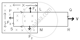
Three forces act on the coil.
F1 on conductor PL ∴ F1 = Bi x, vertically upward.
F2 on conductor MS ∴ F2 = Bi x, vertically downward.
F3 on conductor SP ∴ F3 = Bi L towards left.
F1 and F2 are equal and opposite and also on the same line. They will cancel each other; F3 is a resultant force. The external agent has to do work against this force.
∴ F3 = −Bi l ...(−ve sign indicates that force is opposite to dx.)
If dx is the displacement in time dt, then the work done (dw) = F3 dx.
∴ dw = − BiL dx
This power is an electrical energy ‘ei’ where ‘e’ is an induced e.m.f.
∴ ei = `-(B_i ldx)/(dt)`
∴ e = `-(BLdx)/(dt)`
∴ e = −BLv
∴ e = `-d/dt (BLx)`
∴ e = `(-d phi)/(dt)` ...[from eq (1)]
Lenz’s Law states that the direction of the induced electromotive force (EMF) and the resulting current in a conductor is always such that it opposes the change in magnetic flux that caused it.
Mathematically, Lenz’s Law is expressed as:
ε = `(-d phi_B)/dt`
Where,
ε = Induced EMF
ΦB = Magnetic flux
The negative sign indicates opposition to the change in flux.
State Faraday’s laws of electromagnetic induction.
First law: Whenever there is a change of magnetic flux in a closed circuit, an induced emf is produced in the circuit. This law is a qualitative law as it only indicates the characteristics of induced emf.
Second law: The magnitude of the induced emf produced in the circuit is directly proportional to the rate of change of the magnetic flux linked with the circuit. This law is known as the quantitative law, as it gives the magnitude of the induced emf.
Faraday’s First Law: Whenever the magnetic flux linked with a circuit changes, an emf is induced in the circuit.
Faraday’s Second Law: The magnitude of the induced emf is equal to the rate of change of magnetic flux.
e = `-(d phi)/dt`
For a coil of N turns:
e = `-N (d phi)/dt`
Negative sign indicates Lenz’s law (direction opposes cause).
Statement
The induced EMF in a closed loop has a direction such that the current it drives would create a magnetic flux to oppose the change in flux through the circuit.
Mathematically, this is captured by the negative sign:
Proof (Lenz's Law as Conservation of Energy)
Claim: Lenz's law is a necessary consequence of the Law of Conservation of Energy.
Proof by contradiction:
Suppose, contrary to Lenz's law, the induced current aided the change in flux instead of opposing it.
- When the N-pole of a magnet approaches a coil, the induced current (if aiding) would create a South pole on the near face of the coil
- This South pole would attract the incoming North pole of the magnet
- The magnet would accelerate towards the coil without any external effort
- The accelerating magnet would induce more current, which would attract the magnet even more strongly
- This would result in continuously increasing kinetic energy and electrical energy, generated from nothing
- This is a perpetual motion machine — a direct violation of the Law of Conservation of Energy
Since this is impossible, the induced current must oppose the flux change — Lenz's law is proved.
Conclusion
- Lenz's law is not an arbitrary rule — it is mandated by energy conservation
- The work done by the external agent (to overcome the opposing electromagnetic force) is the source of all electrical energy generated
- Without Lenz's law, electromagnetic induction would violate the most fundamental law of physics
Statement: The mutual inductance of coil 1 with respect to coil 2 equals the mutual inductance of coil 2 with respect to coil 1.
This is called the Reciprocity Theorem of Mutual Inductance.
Implication: It does not matter which coil drives the current — the mutual inductance M between the pair is always the same property of the system, not just one coil.youtube
Two circular loops, one of small radius r and the other of larger radius R, such that R >> r, are placed coaxially with centres coinciding. Obtain the mutual inductance of the arrangement.

Let a current IP flow through the circular loop of radius R. The magnetic induction at the centre of the loop is
BP = `(mu_0I_P)/(2R)`
As, r << R, the magnetic induction BP may be considered to be constant over the entire cross-sectional area of the inner loop of radius r. Hence magnetic flux linked with the smaller loop will be
`Φ_S = B_PA_S = (mu_0I_P)/(2R)pir^2`
Also, ΦS = MIP
∴ M = `Phi_S/I_P = (mu_0pir^2)/(2R)`
A transformer is based on the principle of mutual induction, i.e., whenever the magnetic flux linked with a coil changes, an emf is induced in the neighbouring coil. For an ideal transformer there is no loss of power, so Pinput = Poutput. On the basis of winding, transformers are of two types — step-up and step-down.
Key Points
- Electricity and magnetism are interrelated.
- Electric current can produce a magnetic field.
- A changing magnetic field can produce electric current.
- The production of electric current by a varying magnetic field is called electromagnetic induction.
- Michael Faraday showed in 1831 that a moving magnet can produce current in a conductor.
- The current produced due to electromagnetic induction is called induced current.
- Generators, transformers, induction motors, and wireless chargers work on electromagnetic induction.
- Current is induced in a coil either by flux from a neighbouring coil or by the coil's own changing flux.
- For a closely wound coil, flux linkage = NΦB.
- Inductance L is the constant of proportionality: NΦB = LI.
- L depends only on coil geometry and material properties — not on current.
- Like capacitance, inductance is a scalar with SI unit henry (H) and dimensional formula [ML2T−2A−2].
- A phasor is a rotating vector about the origin with angular speed ω.
- Its vertical component gives the instantaneous value of v or i.
- The length of the phasor equals the peak value (vm or im).
- For a pure resistor: current and voltage are in phase — phasors point in the same direction, phase angle = 0°.
- For inductors, capacitors, or combinations: the current is NOT in phase with voltage — phasors differ in direction.
Inductive Reactance (XL)
- XL= ωL = 2πfL
- Increases with frequency
- Voltage leads current
Capacitive Reactance (XC)
- \[X_C=\frac{1}{\omega C}=\frac{1}{2\pi fC}\]
- Decreases with frequency
- Current leads voltage
- Series circuit with R, L, C
- The same current flows through all components
- Net Reactance: \[X=X_L-X_C=\omega L-\frac{1}{\omega C}\]
- Impedance (Z): \[Z=\sqrt{R^2+(X_L-X_C)^2}\]
- Phase Angle: \[\tan\phi=\frac{X_L-X_C}{R}\]
- Power Factor: \[\cos\phi=\frac{R}{Z}\]
Concepts [27]
- Introduction to Electromagnetic Induction
- The Experiments of Faraday and Henry
- Magnetic Flux
- Faraday's Laws of Electromagnetic Induction
- Lenz’s Law and Conservation of Energy
- Motional Electromotive Force (e.m.f.)
- Energy Consideration: a Quantitative Study
- Eddy Currents or Foucault Currents
- Inductance
- Mutual Inductance
- Self Inductance
- Alternating-Current Generator
- AC Voltage Applied to a Resistor
- Representation of AC Current and Voltage by Rotating Vectors - Phasors
- AC Voltage Applied to an Inductor
- AC Voltage Applied to a Capacitor
- AC Voltage Applied to a Series LCR Circuit
- LC Oscillations
- Transformers
- Peak and Rms Value of Alternating Current Or Voltage
- Reactance and Impedance
- Power in AC Circuit
- Motional and Static EMI and Application of EMI
- Voltage and Power
- Introduction to Ac and Aс Circuits
- LCR Circuit
- Quality and Power Factor
