Definitions [24]
Define a wavefront.
Wavefront is defined as the locus of all the points in space that reach a particular distance by a propagating wave at the same instant.
A wave front is defined as a surface of constant phase.
A wavefront is a surface of constant phase.
If a point source emits waves uniformly in all directions, the locus of points which have the same amplitude and vibrate in the same phase is a sphere. This is known as a spherical wave.
At a large distance from the source, a small portion of the spherical wave can be considered as a plane. This is known as a plane wave.
A rarer medium is a medium in which light travels faster and whose refractive index is lower compared with the denser medium.
The critical angle is the angle of incidence in the denser medium for which the angle of refraction in the rarer medium becomes 90 degrees.
If i = ic, then the refracted ray travels along the boundary surface.
Total internal reflection is the complete reflection of light back into the denser medium when light travels from a denser to a rarer medium, and the angle of incidence becomes greater than the critical angle.
When two or more waves travel through the same medium at the same time, the resultant displacement is the sum of the displacements due to the individual waves.
The redistribution of intensity that occurs when two light waves superpose is called interference.
Sources that emit waves of the same frequency and maintain a constant phase difference are called coherent sources.
Sources for which the phase difference changes randomly with time are called incoherent sources.
When two waves meet in the same phase, the resultant amplitude increases and the intensity becomes maximum.
When two waves meet in opposite phase, the resultant amplitude decreases, and the intensity becomes minimum.
A fringe is a bright or dark band formed on the screen due to constructive or destructive interference.
Interference is the phenomenon in which light intensity is modified due to the superposition of two or more light waves.
Fringe width is the distance between two consecutive bright fringes or two consecutive dark fringes.
Diffraction is the phenomenon of bending of light (or any wave) around the corners or edges of an obstacle or aperture, causing it to spread into the geometrical shadow region and produce alternate dark and bright regions.
A Polaroid is a thin film of ultramicroscopic crystals used to produce plane-polarised light.
An unpolarised wave is one in which the plane of vibration changes randomly in very short time intervals.
The plane of polarisation is the plane in which vibrations are present — it is perpendicular to the plane of vibration and contains the direction of propagation.
Polarisation is the phenomenon of restricting the vibration of a light wave to a particular plane perpendicular to the direction of propagation of the wave, or confining the electric vector vibrations to one direction perpendicular to the direction of propagation.
A transverse wave is one in which the displacement of particles is perpendicular to the direction of propagation of the wave.
A wave in which the electric field vectors are confined in one plane and are parallel to a unique direction is called a linearly polarised wave or plane polarised wave.
The plane of vibration is the plane in which the electric field vector \[\vec{E}\] vibrates or oscillates.
Formulae [6]
For two waves of equal intensity I0, the resultant intensity is:
I = \[4I_0\cos^2\left(\frac{\phi}{2}\right)\]
\[\beta=\frac{\lambda D}{d}\]
\[\alpha=\frac{\beta}{D}=\frac{\lambda}{d}\]
\[x_n-x_m=\left[n-\frac{(2m-1)}{2}\right]\beta\]
\[\begin{array} {cc} & x_m=\frac{(2m-1)\lambda D}{2d} \end{array}\]
\[\begin{array} {c}x_n=\frac{n\lambda D}{d}=n\beta \end{array}\]
Theorems and Laws [3]
With the help of a diagram, show how a plane wave is reflected from a surface. Hence, verify the law of reflection.
According to the laws of reflection:
- At the point of incidence, the incident rays, reflected rays, and normal to the reflecting surface all lie in the same plane.
- On opposing sides of the normal are the incident and reflected rays.
- The angle of incidence and the angle of reflection are the same. i.e., ∠i = ∠r.
Explanation:
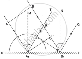
Reflection of light
XY: Plane reflecting surface
AB: Plane wavefront
RB1: Reflecting wavefront
A1M, B1N: Normal to the plane
∠AA1M = ∠BB1N = ∠i = Angle of incidence
∠TA1M = ∠QB1N = ∠r = Angle of reflection
A plane wavefront AB is advancing obliquely towards the plane reflecting surface XY. The AA1 and BB1 are incident rays.
When ‘A’ reaches XY at A1, then the ray at ‘B’ reaches point ‘P’, and it has to cover the distance PB1 to reach the reflecting surface XY.
Let ‘t’ be the time required to cover the distance PB1. During this time interval, secondary wavelets are emitted from A1 and will spread over a hemisphere of radius A1R, in the same medium. The distance covered by secondary wavelets to reach from A1 to R in time t is the same as the distance covered by primary waves to reach from P to B1. Thus, A1R = PB1 = ct.
All other rays between AA1 and BB1 will reach XY after A1 and before B1. Hence, they will also emit secondary wavelets of decreasing radii.
The surface touching all such hemispheres is RB1 which is the reflected wavefront, bounded by reflected rays A1R and B1Q.
Draw A1M ⊥ XY and B1N ⊥ XY.
Thus, the angle of incidence is ∠AA1M = ∠BB1N = i, and the angle of reflection is ∠MA1R = ∠NB1Q = r.
∠RA1B1 = 90 − r
∠PB1A1 = 90 − i
In ΔA1RB1 and ΔA1PB1
∠A1RB1 = ∠A1PB1
A1R = PB1 ...(Reflected waves travel an equal distance in the same medium in equal time.)
A1B1 = A1B1 ....(Common side)
∴ ΔA1RB1 ≅ ΔA1PB1
∴ ∠RA1B1 = ∠PB1A1
∴ 90 − r = 90 − i
∴ i = r
Also from the figure, it is clear that incident rays, reflected rays, and normal lie in the same plane.
This explains the laws of reflection of light from a plane reflecting surface on the basis of Huygen’s wave theory.
Frequency, wavelength, and speed of light do not change after reflection. If reflection takes place from a denser medium, then the phase changes by π radians.
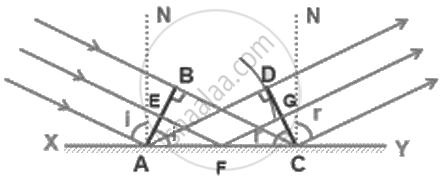
AB = Incident wavefront
CD = Reflected wavefront
XY = Reflecting surface
If c be the speed of light and t be the time taken by light to go from B to C or A to D or E to G through F, then
t = `(EF)/C + (FG)/C`
= `(AF sin i)/C + (FC sin r)/C`
= `(AC sin r + AF(sin i - sin r))/C`
For rays of light from different parts of the incident wavefront, the values of AF are different. But light from different points of the incident wavefront should take the same time to reach the corresponding points on the reflected wavefront.
So, ‘t’ should not depend upon AF.
This is possible only if sin i – sin r = 0.
i.e., sin i = sin r
⇒ i = r
Hence proved.
Statement
When a beam of plane polarised light is incident on an analyser, the intensity of the transmitted light is directly proportional to the square of the cosine of the angle θ between the pass-axis of the analyser and the plane of polarisation of the incident light.
Where:
- I0 = intensity of plane-polarised light incident on the analyser
- I = intensity of the transmitted light
- θ = angle between the pass axes of the polariser and analyser
Step 1: Set up
- Let plane-polarised light with amplitude a and intensity I0 be incident on analyser P2. The pass-axis of P2 makes an angle θ with the pass-axis of P1.
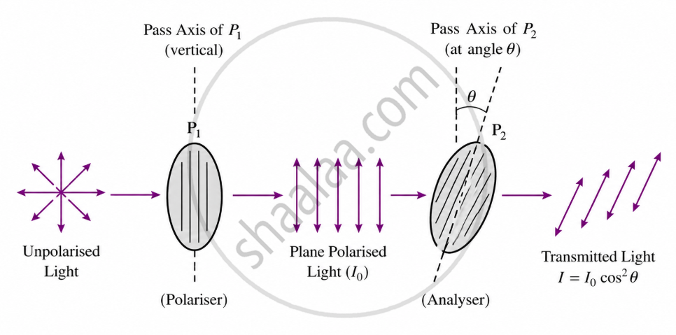
Step 2: Resolve the amplitude
The electric field amplitude aaa is resolved into two rectangular components relative to P2's pass-axis:
- Component parallel to P2's pass-axis: a cos θ → transmitted
- Component perpendicular to P2's pass-axis: a sin θ → absorbed/blocked
Step 3: Calculate transmitted intensity
Since only the parallel component passes through, and intensity ∝ (amplitude)2:
- I ∝ (a cos θ)2 = a2 cos2 θ
Step 4: Substitute I0
Since I0 ∝ a2 (the maximum intensity when θ = 0°):
- I = I0 cos2 θ
Statement:
When unpolarised light is incident at polarising angle iB on an interface separating air from a medium of refractive index μ, then the reflected light is plane polarised (perpendicular to the plane of incidence), provided:
Additional condition at polarising angle:
i.e., the reflected plane polarised light is at right angles to the refracted light.
OR
Statement:
- When the angle of incidence equals the polarising angle (θB), the reflected and refracted rays are perpendicular to each other.
- "The refractive index of a medium is equal to the tangent of the polarising angle θB."
Key Points
- Wave optics studies the wave nature of light.
- Newton supported the corpuscular theory of light.
- Huygens proposed the wave theory in 1678.
- Young's 1801 interference experiment supported the wave model.
- Maxwell explained light as an electromagnetic wave.
- Geometrical optics treats light as rays.
- Wave optics includes Huygens' principle, interference, diffraction, and polarisation.
